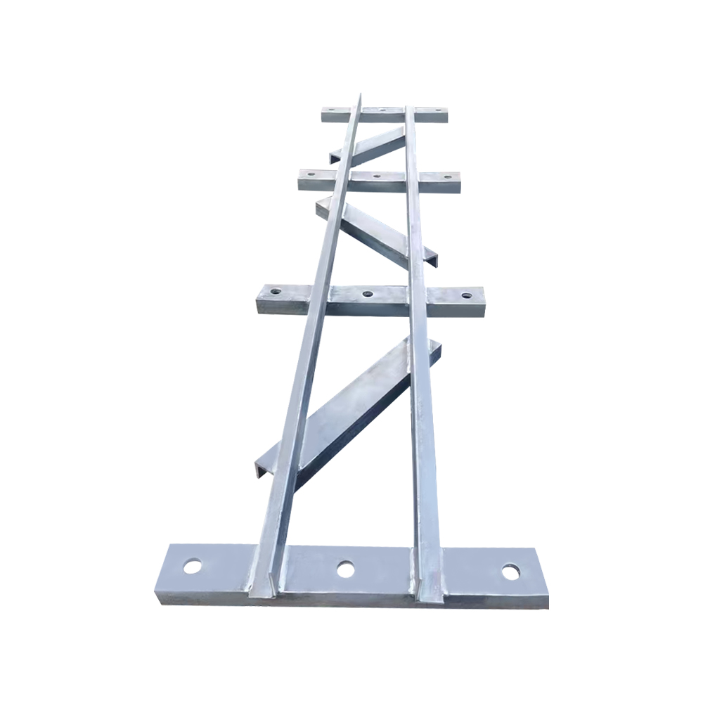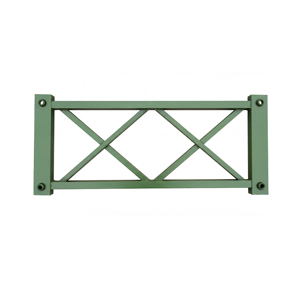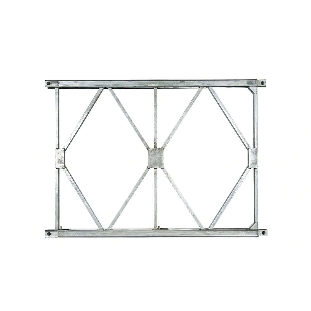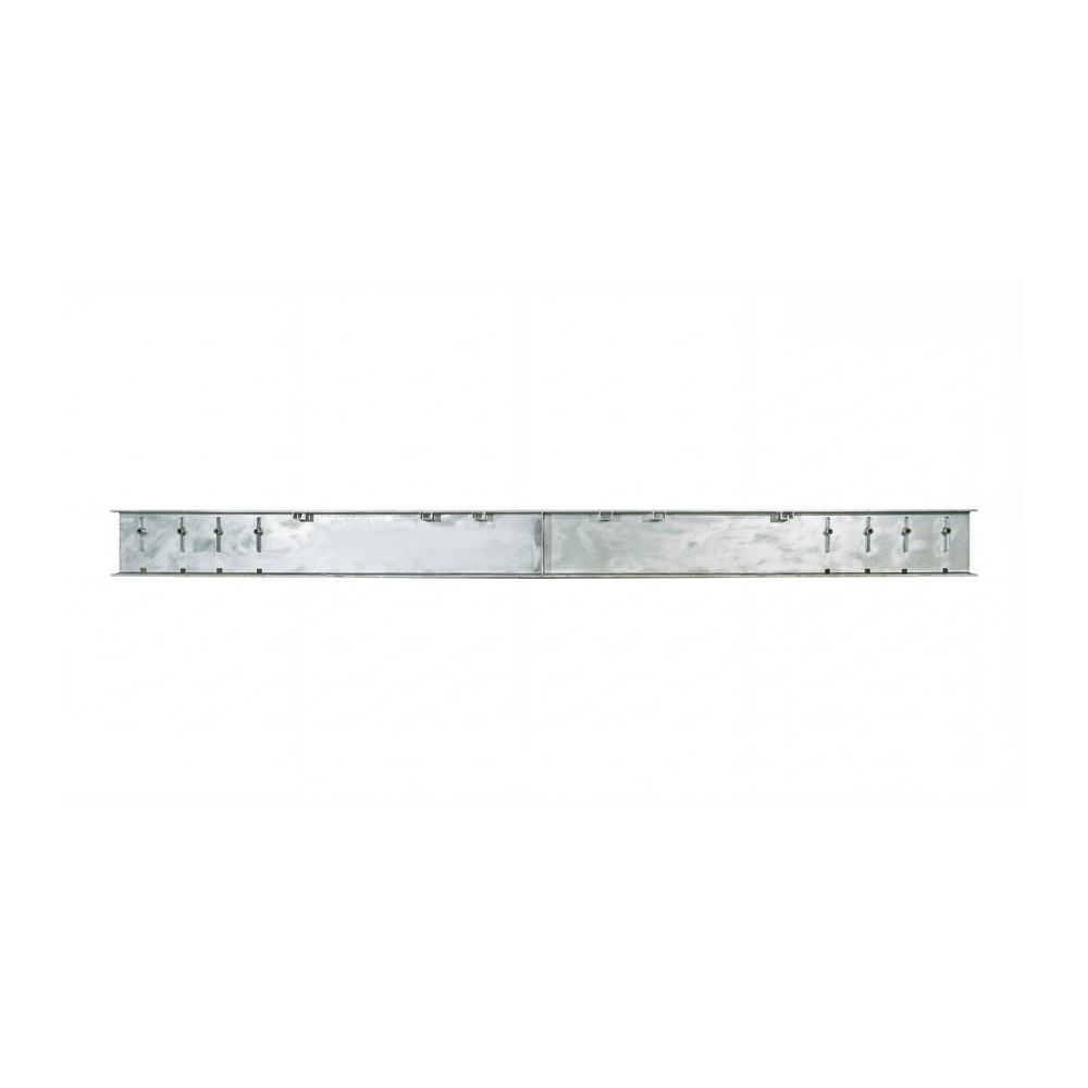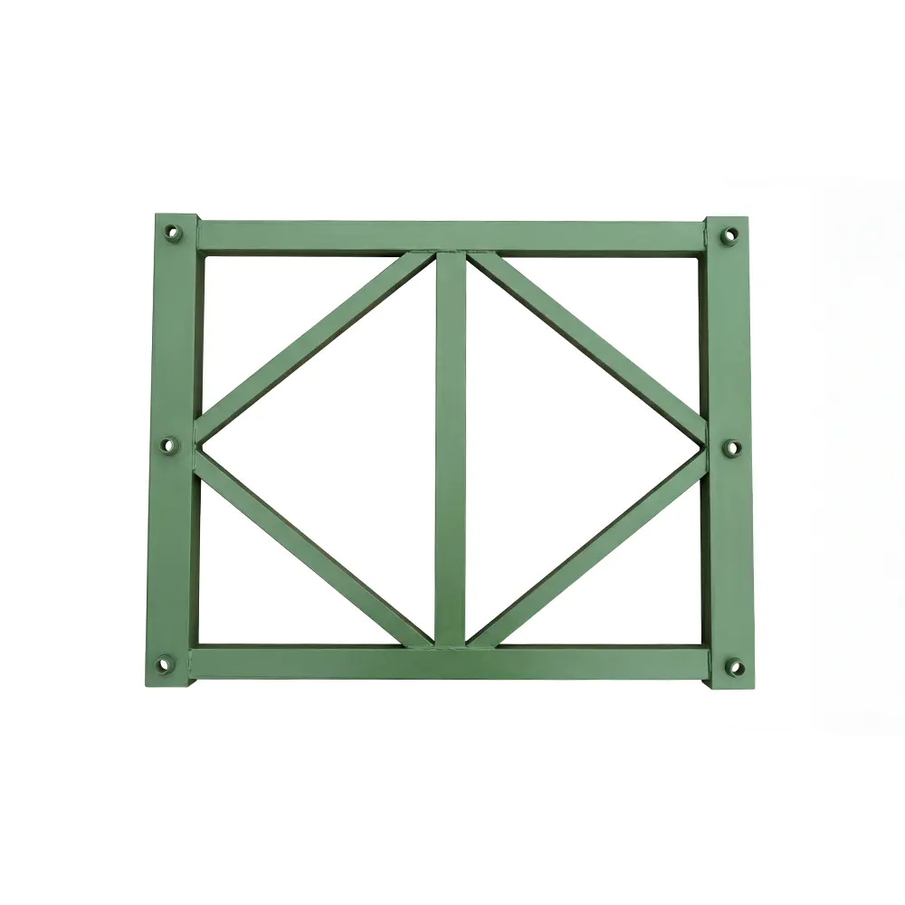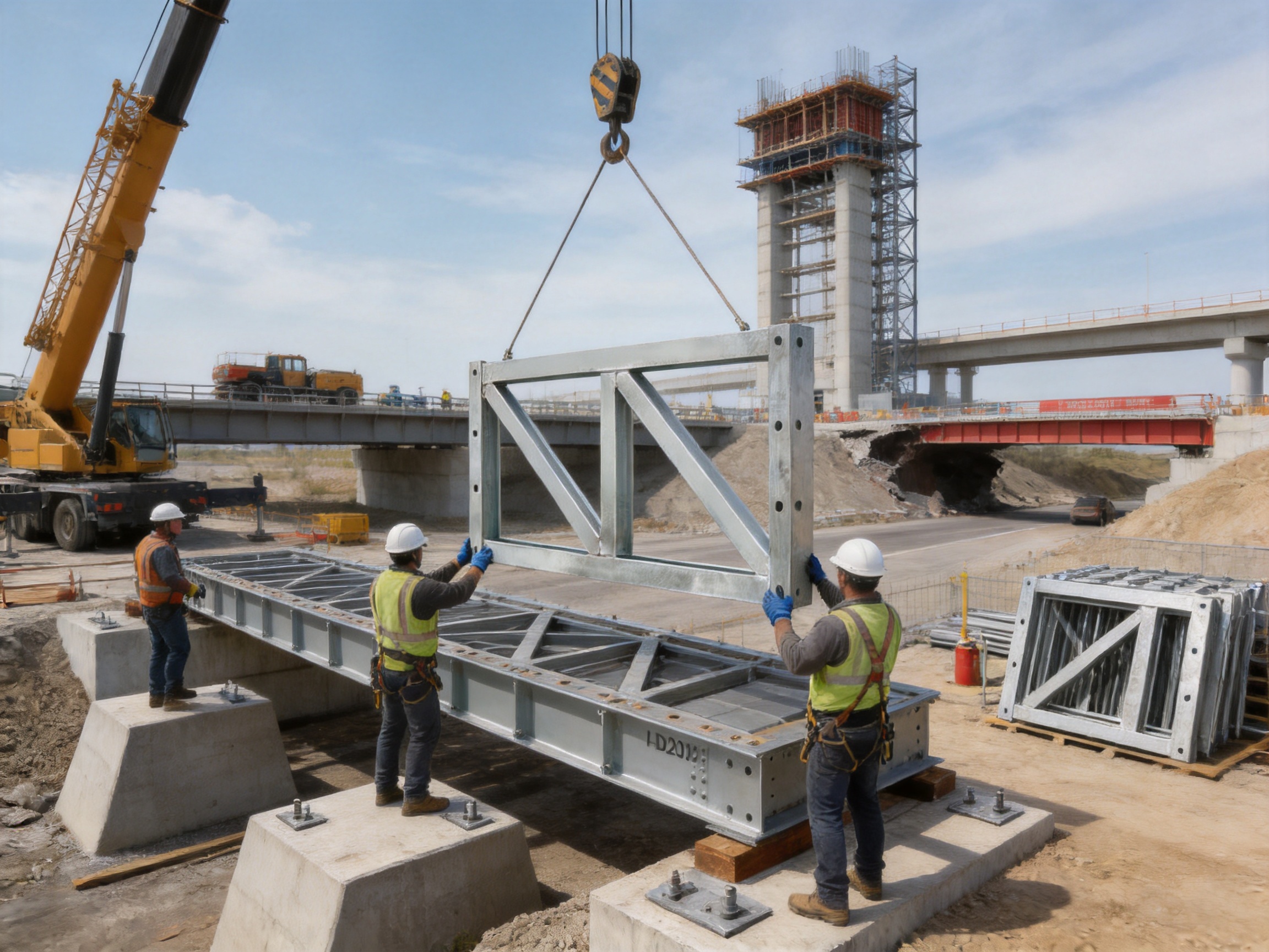
The HD200 Vertical Support Frame is a structural support component developed for heavy-duty modular bridge systems, prefabricated steel bridges, large formwork assemblies, and temporary or semi-permanent engineering structures. Although compact in appearance, the frame performs a critical role in the overall load-bearing system. It helps transfer vertical forces, controls structural deformation, improves resistance to overturning, and connects the main truss arrangement with horizontal support frames and strengthening chords.
In a properly designed HD200 bridge system, the vertical support frame is not an isolated accessory. It forms part of a three-dimensional structural network in which truss sections, chords, connecting members, bracing, deck systems, and foundation supports work together. The result is a modular load-bearing arrangement that can be adapted to different spans, loading requirements, site conditions, and construction sequences.
This article examines the function, specifications, manufacturing characteristics, application value, installation considerations, and competitive advantages of the HD200 Vertical Support Frame. It also explains how a specialized manufacturer can support customers through fabrication, engineering coordination, quality management, customized production, and project-level technical service.
1. Product Overview
The Type HD200 Vertical Support Frame for Bailey bridges is a vertical load-bearing component used in HD200 prefabricated steel bridge and heavy-duty truss systems. Its principal purpose is to receive and distribute vertical loads within the truss assembly while helping maintain the intended geometry of the bridge or support structure.
During service, the frame may be exposed to loads generated by bridge traffic, construction equipment, temporary storage, formwork, wind effects, erection activities, and other project-specific actions. The vertical support frame transfers these forces through the connected structural members toward the foundation or supporting substructure.
Its performance is especially important where the structure has a large span, a high load demand, a considerable height-to-width ratio, or a limited foundation footprint. In these situations, a support component must do more than simply carry compression. It must also contribute to overall stability, resist distortion, maintain alignment, and cooperate with the rest of the modular system.
The HD200 Vertical Support Frame is available in two primary specifications: the 730 type and the 480 type. These two versions correspond to different HD200 truss spacing arrangements. This compatibility allows engineers and contractors to select a frame that matches the geometry of the selected bridge or support configuration.
2. Key Technical Specifications
| Item |
Model 730 |
Model 480 |
| Product |
HD200 Vertical Support Frame |
HD200 Vertical Support Frame |
| External dimensions |
1774 × 820 × 50 mm |
1774 × 570 × 50 mm |
| Center distance dimensions |
1694 × (250 + 230 + 250) mm |
Configured for the corresponding HD200 spacing arrangement |
| Material |
Q355B steel |
Q355B steel |
| Primary function |
Vertical load transfer and structural stabilization |
Vertical load transfer and structural stabilization |
| Typical system |
HD200 prefabricated steel bridge and heavy-duty truss system |
HD200 prefabricated steel bridge and heavy-duty truss system |
The dimensions provided above are product reference dimensions. Final selection should always be based on the approved structural design, the exact truss arrangement, the required load class, the support spacing, and the project installation method.
3. Structural Function of the Vertical Support Frame
3.1 Transfer of Vertical Loads
The most direct function of the vertical support frame is to transfer vertical forces through the bridge or truss system. Traffic loads, deck loads, construction loads, and the self-weight of the superstructure create reactions that must travel through a continuous load path.
The frame helps establish this load path between upper structural elements and lower support members. By distributing forces through connected components, it reduces the risk of concentrated loading at individual connection points. This is particularly valuable in modular structures, where repeated units must act together rather than behave as unrelated pieces.
3.2 Control of Vertical Deformation
All steel structures experience some degree of deflection under load. Excessive or uneven deformation, however, can affect serviceability, alignment, riding comfort, connection performance, and construction safety. A correctly positioned vertical support frame helps maintain the designed elevation and spacing of the HD200 system.
It works with horizontal support frames, strengthening chords, lateral bracing, and truss panels to control the shape of the assembled structure. The combined system improves stiffness and helps prevent local displacement from developing into a larger global deformation.
3.3 Resistance to Overturning and Instability
Bridge and truss systems may be exposed to lateral wind, eccentric traffic, construction-stage imbalance, impact effects, or uneven support reactions. These forces can produce overturning moments or lateral movement. The vertical support frame contributes to the three-dimensional stability of the system by connecting load-bearing levels and helping maintain the relative position of the truss members.
Its stabilizing effect is enhanced when it is correctly combined with horizontal frames and strengthening chords. These members create a more complete force-bearing arrangement, allowing vertical, horizontal, and lateral forces to be distributed across multiple components.
3.3 Integration with Strengthening Chords
Strengthening chords are used to increase the capacity or stiffness of a truss system. The vertical support frame forms a functional relationship with these chords by helping transfer forces between different structural levels. Together, they can create a closed load-bearing loop that improves the overall behavior of the assembled system.
This coordinated arrangement is important in heavy-load applications. A vertical frame alone cannot solve every structural problem, but a vertical frame integrated with strengthening chords and horizontal support frames can provide a more stable and predictable load path.
4. Why the HD200 Configuration Is Suitable for Heavy-Duty Work
The HD200 system is designed for applications that require greater structural capacity and stability than a basic light modular bridge arrangement can provide. It is suitable for large-span bridge configurations from approximately 9.144 to 60.96 meters and for high-load engineering situations such as HS25-class applications and above, subject to project-specific design verification.
The HD200 arrangement is useful when a project requires a combination of modularity, transportability, erection efficiency, and significant load-bearing capability. It can be assembled from standardized components while still allowing engineers to modify the structural configuration according to span length, width, traffic requirements, support conditions, and construction sequence.
The vertical support frame strengthens this concept by providing a defined component for vertical stability. Instead of relying only on the main truss panels, the system can use dedicated support elements to improve structural interaction between the upper and lower portions of the bridge or temporary support structure.
For contractors, this can simplify project planning. A standardized support component is easier to identify, store, inspect, transport, replace, and integrate into a modular inventory than a highly specialized one-off fabricated member. It can also support repeated use across different projects when the design conditions are compatible.
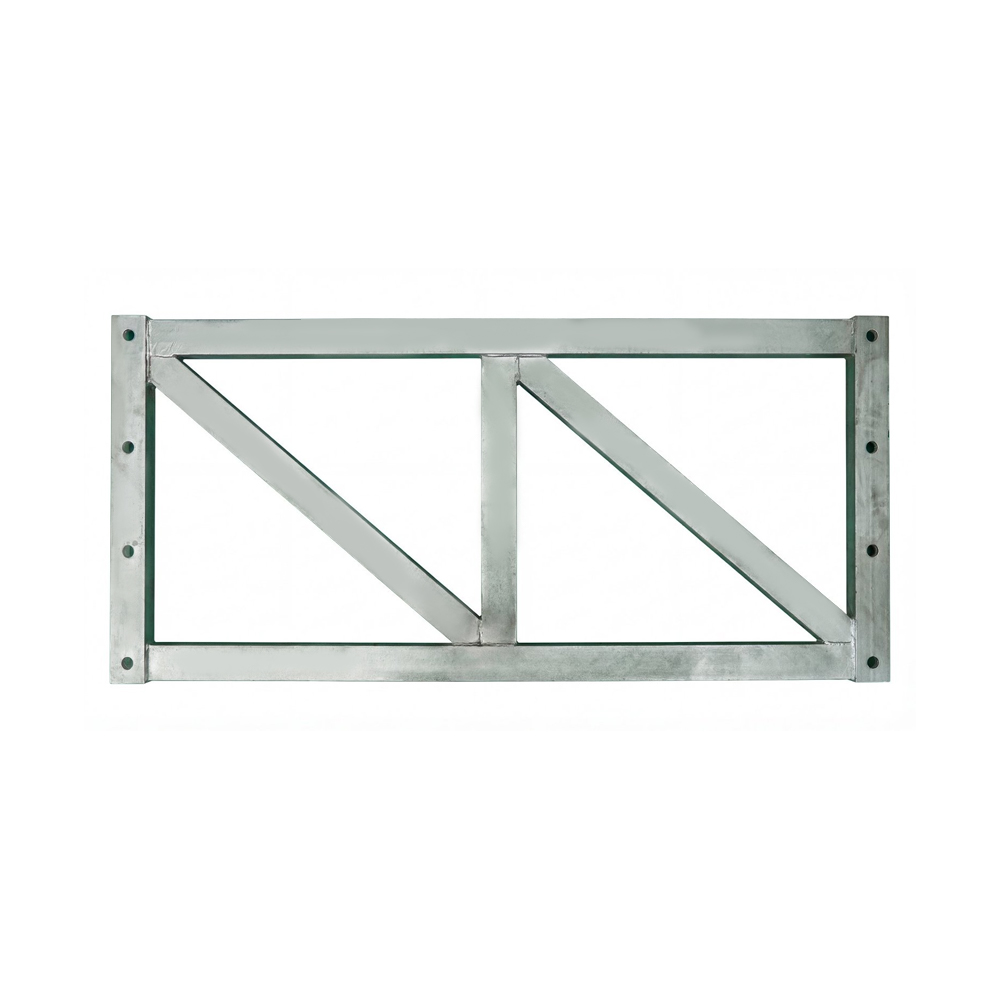
Type HD200 - Vertical Support Frame For Bailey Bridge
5. Material Selection: Q355B Steel
The HD200 Vertical Support Frame is manufactured from Q355B steel. This material is widely used in structural steel applications where a combination of strength, weldability, toughness, and fabrication suitability is required.
Material selection affects more than nominal strength. The steel must be suitable for cutting, forming, drilling, welding, surface preparation, handling, and long-term service. Q355B provides a practical balance for modular bridge components because it can support robust structural fabrication while remaining compatible with common industrial manufacturing processes.
For a bridge support frame, material traceability is essential. Steel plates and sections should be identified through mill certificates or equivalent documentation. A controlled manufacturing process should ensure that the material used in production corresponds to the approved design and specified grade.
Material quality also influences connection behavior. The frame must work with bolts, pins, gusset plates, chords, brackets, and other steel components. Consistent material properties help reduce uncertainty in fabrication and assembly, particularly when multiple frames are used in the same structure.
5.1 Strength and Service Performance
The strength of Q355B steel supports the use of the frame in demanding load-bearing systems. Nevertheless, the safe capacity of the completed bridge depends on many factors, including member arrangement, connection details, unsupported length, bracing, load distribution, foundation conditions, corrosion protection, and erection quality.
For this reason, the material grade should be understood as one part of the engineering solution rather than a guarantee of performance under every condition. Proper design calculation and inspection remain necessary for each application.
5.2 Weldability and Fabrication Suitability
The material is suitable for controlled welding and structural fabrication when correct procedures are followed. Welding parameters, joint preparation, preheating requirements, consumables, welder qualifications, and inspection methods should be determined according to the approved manufacturing procedure.
Good welding practice is especially important at connection zones, corners, stiffener intersections, and areas where force is transferred between plates. Controlled fabrication reduces the possibility of distortion, incomplete fusion, undercut, excessive residual stress, or dimensional deviation.
6. Manufacturing Process and Quality Control
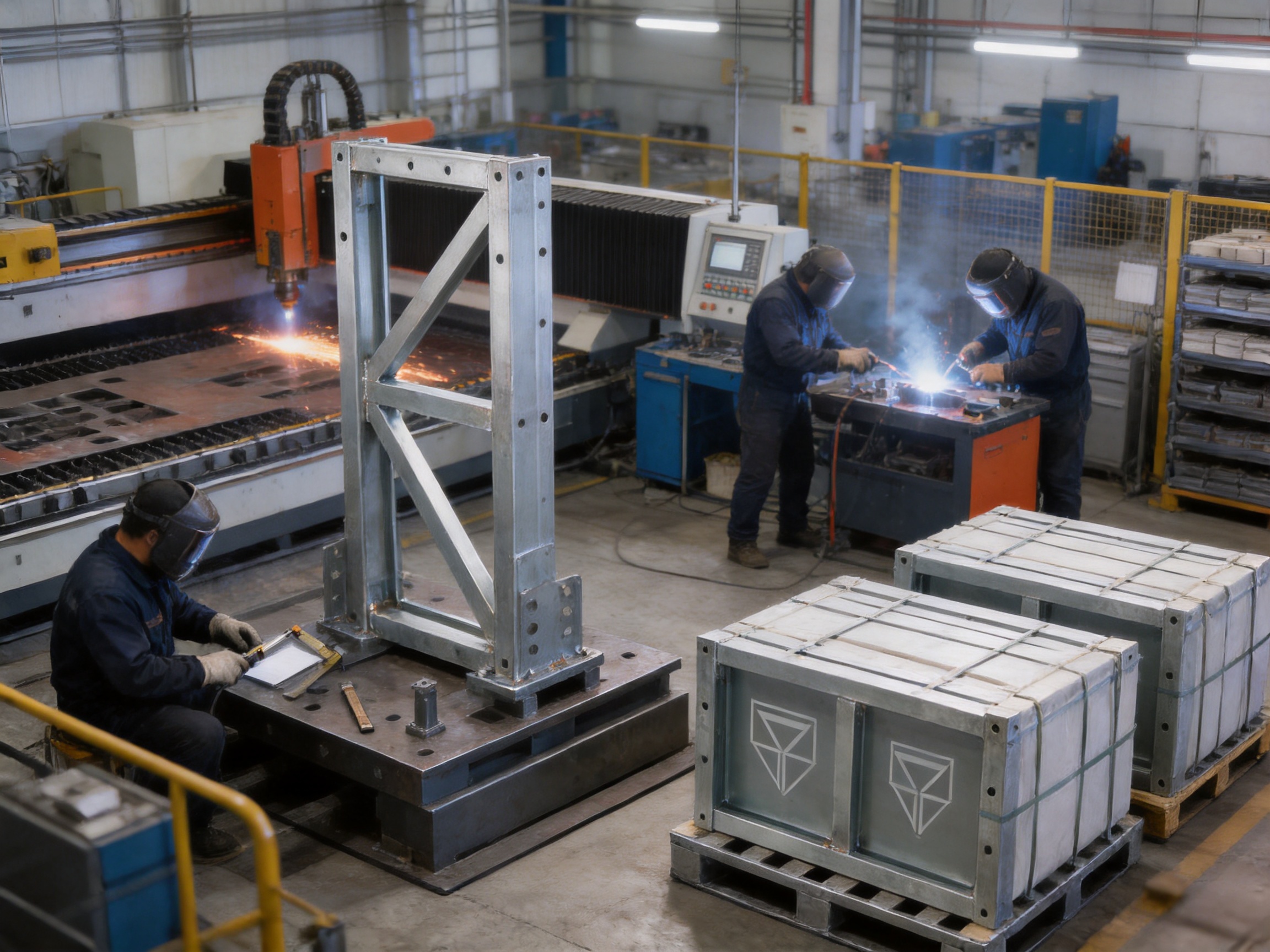
The performance of a vertical support frame depends on both its design and the consistency of its manufacturing process. A specialized steel structure manufacturer should manage the product through a sequence of controlled operations rather than treating it as a simple cut-and-weld assembly.
6.1 Engineering Review and Production Preparation
Manufacturing begins with a review of the product drawings, dimensions, connection requirements, material grade, tolerances, and intended system configuration. The production team should confirm whether the 730 type or 480 type is required and whether the frame must match other HD200 components already available at the project site.
At this stage, the manufacturer can identify potential conflicts between the design and the fabrication process. Examples include difficult weld access, insufficient allowance for distortion, inconsistent hole positioning, unsuitable lifting points, or unclear dimensional references.
Production planning should also determine the required cutting list, welding sequence, inspection points, surface treatment requirements, packing method, and marking system. This preparation improves repeatability and reduces the risk of errors during mass production.
6.2 Steel Cutting and Component Preparation
Steel plates and sections are cut according to approved dimensions. Depending on the production facility, cutting may be performed by CNC plasma, flame cutting, mechanical shearing, or other suitable methods. CNC equipment can improve repeatability for repeated frame components and help maintain consistent geometry across a batch.
After cutting, edges may require cleaning, grinding, straightening, or preparation for welding. Burrs, slag, sharp projections, and excessive heat distortion should be removed. Correct edge preparation supports sound weld formation and reduces the need for extensive rework.
6.3 Assembly and Dimensional Control
Assembly fixtures are valuable when producing repeated modular bridge components. A fixture can hold plates and stiffeners in the correct relationship while tack welding and final welding are carried out. This helps control the external dimensions, center distances, connection locations, and squareness of the frame.
Dimensional control should not be limited to the overall length and width. Important checks may include hole spacing, plate alignment, diagonal measurements, flatness, perpendicularity, weld access, and the position of attachment points. These details directly affect installation efficiency and compatibility with other HD200 components.
6.4 Welding and Welding Inspection
Welding should be carried out using documented procedures and qualified personnel. The welding sequence should be planned to minimize distortion and residual stress. When necessary, the frame can be welded from balanced sides or in a sequence that distributes heat input across the assembly.
Visual inspection is the first level of welding quality control. Inspectors should examine weld continuity, profile, surface defects, cracks, porosity, undercut, overlap, and spatter. Depending on the design and project requirements, additional non-destructive testing may be applied to selected welds or critical joints.
Inspection records should be retained as part of the production documentation. These records can include material certificates, welding procedure information, welder qualifications, dimensional inspection reports, and non-destructive testing results.
6.5 Surface Treatment and Corrosion Protection
Steel bridge components may be exposed to rain, humidity, dust, road spray, salt, construction chemicals, and repeated handling. Surface treatment therefore plays an important role in extending service life.
A typical process may include surface cleaning, abrasive preparation, primer application, intermediate coating, and finishing coating. The exact coating system should be selected according to the expected environment and project requirements.
Before coating, the steel surface should be free from oil, moisture, loose rust, welding slag, and other contaminants. Coating thickness, drying time, environmental conditions, and repaired areas should be controlled during production.
6.6 Final Inspection, Marking, and Packing
Before dispatch, each frame should undergo a final inspection. The inspection may verify dimensions, material identification, weld quality, surface condition, coating coverage, connection features, and product markings.
Clear marking helps contractors identify the component during transport and erection. Markings may include the product type, model, production batch, part number, and other traceability information. Proper packing reduces the risk of impact damage, deformation, coating abrasion, or loss of small connection accessories during shipment.
7. Advantages Compared with Less Specialized Alternatives
The HD200 Vertical Support Frame offers several advantages when compared with improvised support members, non-standard fabricated frames, or components that are not specifically designed for HD200 truss geometry.
7.1 Purpose-Built System Compatibility
A major advantage is compatibility with the HD200 modular truss system. The frame is designed around the corresponding spacing and connection arrangement rather than being adapted from a general-purpose steel bracket.
This compatibility can reduce adjustment work during erection. When the dimensions, connection positions, and structural interfaces are coordinated, workers can assemble the system more efficiently and with fewer site modifications.
7.2 Two Model Options
The availability of 730 and 480 models provides flexibility for different HD200 truss spacing requirements. A single fixed-size support frame may not be suitable for every bridge configuration. Offering two coordinated specifications allows the system to accommodate different structural layouts without abandoning standardization.
7.3 Stronger Three-Dimensional Stability
Compared with a simple vertical post or isolated plate support, the HD200 frame is intended to function as part of a three-dimensional system. It works with horizontal support frames and strengthening chords to create a more complete structural arrangement.
This is important where a structure may be affected by lateral movement, uneven loading, or a high height-to-width ratio. The frame helps connect different levels of the system and contributes to resistance against deformation and overturning.
7.4 Better Suitability for Repeated Deployment
Modular bridge components are often erected, dismantled, transported, stored, and reused. A standardized vertical support frame is suitable for this type of project cycle. Its repeatable geometry supports inventory management and allows contractors to plan component quantities more efficiently.
Repeated deployment also makes inspection important. Each frame should be checked for dents, cracks, excessive corrosion, hole elongation, weld defects, and permanent deformation before reuse. The benefit of modularity is greatest when the components are maintained through a disciplined inspection program.
7.5 Reduced Dependence on Site Fabrication
Using a prefabricated support frame can reduce the amount of cutting, drilling, and welding required at the project site. This can improve safety and shorten the erection schedule, especially in locations where access is restricted or hot work is difficult.
Factory fabrication also provides a more controlled environment for dimensional inspection, welding, surface treatment, and documentation. Site work can then focus on assembly, alignment, connection tightening, launching, and final verification.
7.6 Adaptability for Different Engineering Uses
The frame can support more than one narrow application. In addition to temporary and semi-permanent bridge structures, it may be used in heavy-duty truss systems, large formwork support arrangements, construction staging systems, and emergency rescue structures, provided the design confirms suitability.
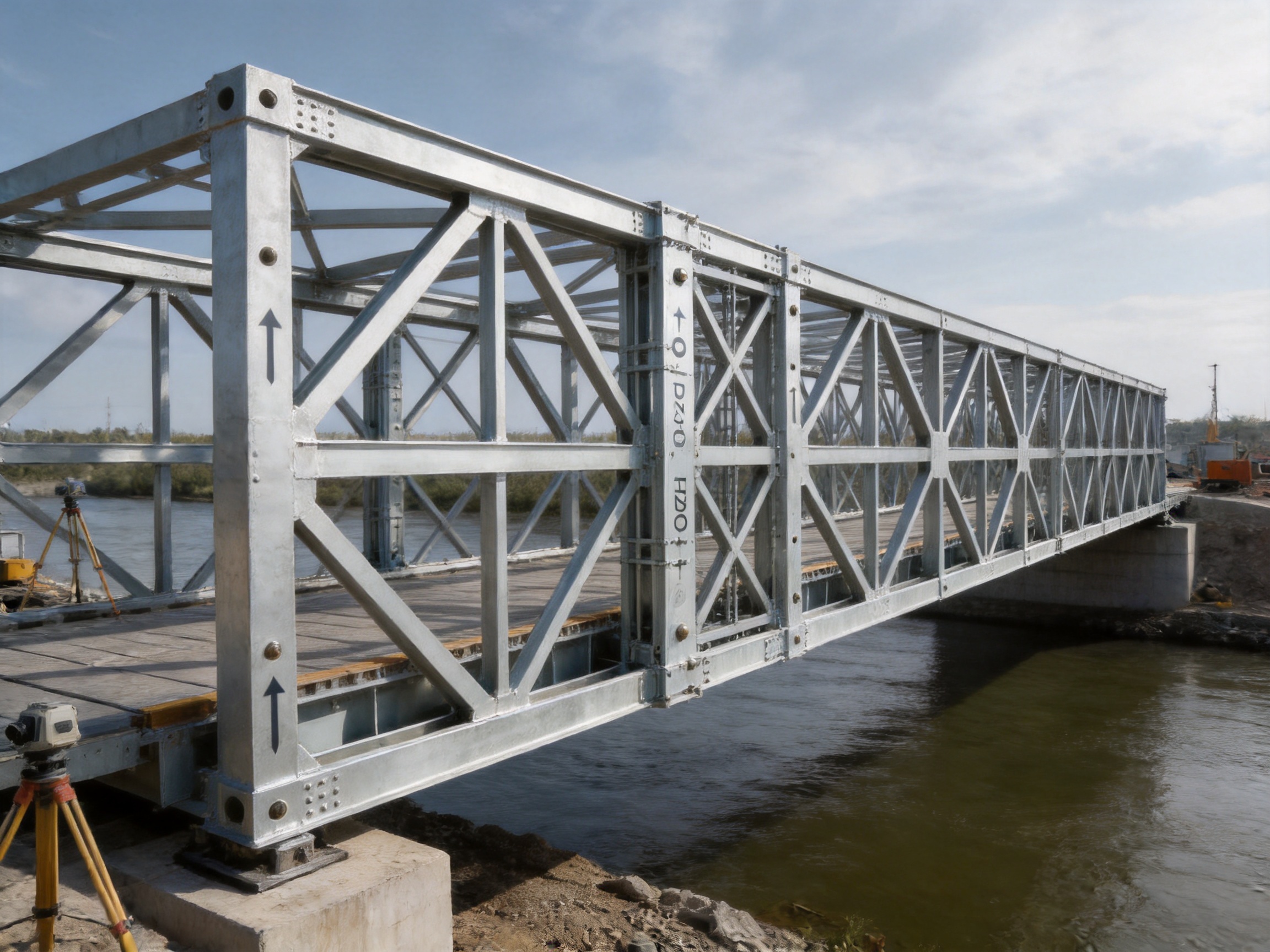
8. Application in Bridge Engineering
8.1 Temporary and Emergency Bridges
Temporary and emergency bridges are often required when an existing crossing has been damaged, when construction traffic must be maintained, or when a permanent bridge is under repair. In these situations, speed of deployment and predictable component compatibility are highly valuable.
The HD200 Vertical Support Frame contributes to a stable modular assembly that can be erected using standardized truss sections and connection components. Its use can help create a dependable vertical load path while allowing the bridge to be adapted to the available span and site conditions.
Emergency projects may involve difficult terrain, limited equipment, uncertain foundation conditions, and strict time constraints. These challenges make pre-engineered modular components useful. However, emergency deployment still requires competent structural assessment, foundation verification, load control, and inspection before opening the bridge to traffic.
8.2 Semi-Permanent Bridge Systems
Some projects require a bridge to remain in service for an extended period before a permanent structure is completed. A semi-permanent modular bridge must be designed with suitable corrosion protection, inspection access, traffic management, drainage, foundation support, and maintenance procedures.
The vertical support frame can form part of this longer-term arrangement by helping stabilize the truss structure and transfer loads to the supports. The duration of service should be considered when selecting coating systems, connection protection, inspection intervals, and replacement strategies.
8.3 Construction Access Bridges
Construction sites may need access bridges for trucks, cranes, material transport, or worker movement. These bridges can experience concentrated wheel loads, frequent loading cycles, impact, mud, water, and irregular traffic patterns.
The HD200 system is suitable for such demanding environments when the bridge is designed for the actual vehicle class and loading conditions. The vertical support frame supports the structural arrangement, while the deck, bracing, foundation, and connections must be checked for the complete load case.
8.4 Bridge Construction Support
During bridge construction, temporary structures may be required to support formwork, materials, equipment, or partially completed bridge elements. The vertical support frame may be integrated into a temporary support tower or truss arrangement.
Construction-stage structures can experience load conditions that differ from the completed bridge. The design should consider lifting, launching, temporary eccentricity, incomplete bracing, wind during erection, and the sequence in which components are installed. The frame can contribute to stability, but only when the complete temporary works design is properly coordinated.
9. Application in Large Formwork Support Systems
Large bridge formwork systems require reliable support because fresh concrete can create substantial temporary loads. Additional forces may result from workers, reinforcement, pumps, vibration, wind, construction equipment, and accidental impact.
The HD200 Vertical Support Frame can be used in a heavy-duty support arrangement for large formwork when engineered for the required load and geometry. Its modular dimensions may simplify the construction of repeated support towers or truss-based formwork systems.
In formwork applications, settlement and deflection control are especially important. Excessive movement can affect concrete geometry, reinforcement cover, surface quality, and worker safety. The vertical support frame works with horizontal members and strengthening components to create a more stable support structure.
Before concrete placement, the completed support system should be inspected for alignment, connection security, bracing, foundation bearing, and access. A controlled loading sequence may also be required to reduce sudden or uneven force application.
10. Application in Emergency Rescue and Disaster Response
Following floods, earthquakes, landslides, storms, industrial incidents, or infrastructure failure, modular steel bridge components may be needed to restore access quickly. A support frame that is strong, standardized, and transportable can be valuable in these circumstances.
The HD200 Vertical Support Frame can contribute to emergency bridge or temporary access structures where a stable vertical load path is required. It can also be used in certain temporary support or rescue access arrangements, subject to engineering review.
Disaster response conditions often involve uncertain ground, debris, poor access, and changing loads. Therefore, the frame should not be installed solely based on visual judgment. Engineers must evaluate the foundation, span, support reactions, vehicle loads, lateral stability, flood effects, and possible scour.
The benefit of a modular product in emergency work is that it can be combined with existing bridge inventories and transported as part of a coordinated response system. Clear product identification and compatibility with standard HD200 components can reduce confusion during urgent deployment.
11. Engineering Considerations Before Installation
11.1 Structural Design Verification
The bridge or truss system must be designed for the actual span, width, traffic classification, load combination, environmental conditions, and support arrangement. The vertical support frame should be included in the calculation model or structural verification process.
Important checks may include axial compression, bending, shear, local plate behavior, buckling, connection resistance, frame stability, overall truss behavior, and foundation reactions. The design should also consider construction-stage loads and accidental conditions where relevant.
11.2 Foundation and Bearing Conditions
A strong steel frame cannot compensate for an inadequate foundation. The supporting ground, concrete pedestal, pile cap, abutment, or temporary bearing arrangement must be capable of receiving the design reactions without excessive settlement, sliding, rotation, or bearing failure.
Where foundation bearing capacity is limited, the project may require wider bearing areas, ground improvement, additional piles, load distribution plates, or a revised support arrangement. The vertical support frame can help create a more complete load path, but foundation engineering remains a separate and essential responsibility.
11.3 Alignment and Level Control
Correct alignment is required for efficient assembly and predictable structural performance. The supports should be positioned according to the approved layout, and the elevation difference between support points should be controlled.
During erection, survey equipment may be used to confirm centerlines, elevations, spacing, verticality, and bridge geometry. Improper alignment can create unintended secondary forces and make connection installation more difficult.
11.4 Connection Inspection
Bolts, pins, locking devices, and other connection components should be inspected before installation. Damaged or heavily worn connection parts should not be used. Bolt tightening, pin installation, retaining devices, and connection gaps should comply with the approved erection procedure.
Connections should also be rechecked after the structure has been loaded or after initial settlement. In reusable modular systems, connection holes and bearing surfaces should be inspected regularly for elongation, deformation, corrosion, and excessive wear.
12. Manufacturing and Service Strengths of the Supplier
The manufacturer behind the HD200 Vertical Support Frame provides a combination of product fabrication and engineering support. Its business covers the design, manufacture, erection, and leasing of Bailey bridges, bridge launching gantries, hanging baskets, pier formwork, and various steel formwork products.
This broad product range is valuable because many bridge projects involve several temporary works systems at the same time. A customer may require a bridge crossing, a launching arrangement, pier formwork, access structures, or construction support. Experience across related steel systems allows the supplier to understand how individual components interact within a larger project.
12.1 Experience with Modular Bridge Systems
The supplier produces Type 321 Bailey truss sections, HD200 or Type 200 Bailey truss sections, bridge support components, and related structural members. This product experience supports better coordination between the vertical support frame and the truss sections, chords, decking, bracing, and other accessories used in the same system.
Manufacturers that understand the complete modular system can help identify compatibility issues earlier than a general metalworking supplier. They can also provide practical information about assembly, transport, component interchangeability, storage, and project sequencing.
12.2 Customized Fabrication
Although the HD200 Vertical Support Frame is available in standardized 730 and 480 versions, projects may still require customized fabrication or coordinated accessories. Customization may involve special markings, coating systems, packaging, connection components, lifting arrangements, or integration with a project-specific support structure.
Customization should be based on approved drawings and engineering review. The objective is not to modify critical structural dimensions without control, but to adapt the product responsibly to the needs of the project while preserving system compatibility and safety.
12.3 Design and System Planning
Technical support can include preliminary system planning, component selection, span arrangement, erection sequence coordination, and interface review. This is particularly useful for contractors that need to organize a complete temporary bridge system rather than purchase a single component.
A system-level approach can reduce procurement gaps. For example, the required number of vertical frames, horizontal frames, strengthening chords, truss panels, deck components, bracing members, connections, and spare parts can be considered together.
12.4 Erection and Technical Assistance
For projects requiring support beyond fabrication, erection and technical assistance may be available. Field support can help contractors follow the approved assembly sequence, confirm component orientation, verify connection installation, and identify potential issues before loading.
Technical support is especially helpful for unusual spans, restricted sites, emergency projects, or structures that combine bridge and formwork functions. It can also help customers improve their internal procedures for inspection, maintenance, and reuse.
12.5 Quality Management
Quality management should cover the full product cycle, including raw material procurement, production planning, welding, dimensional inspection, surface treatment, final acceptance, packing, delivery, and after-sales support.
A consistent quality system improves product interchangeability. When multiple frames are manufactured to the same controlled dimensions, contractors can assemble, replace, and rearrange components with greater confidence.
13. Logistics, Storage, and Reuse
The modular nature of the HD200 Vertical Support Frame makes logistics an important part of its value. The frame should be packed in a way that protects connection areas, coated surfaces, corners, and flatness during loading and transportation.
During storage, components should be placed on stable supports above standing water and mud. They should be separated to allow ventilation and inspection. Heavy objects should not be placed on top of the frame if there is a risk of permanent deformation.
Storage areas should be organized by product type and model. The 730 and 480 versions should be clearly identified so that the correct components are selected during erection. Records should be maintained for delivery, usage, inspection, repair, and return to storage.
Before reuse, the frame should be checked for:
Permanent bending, twisting, or distortion.
Cracks in plates, welds, stiffeners, and connection zones.
Corrosion that reduces effective thickness.
Elongated, damaged, or blocked connection holes.
Worn or damaged bearing surfaces.
Coating failure and exposed steel.
Missing identification marks or traceability information.
Components that do not satisfy the project inspection criteria should be repaired, tested, downgraded, or removed from service according to the responsible engineer’s decision.
14. Sustainability and Lifecycle Value
Reusable steel bridge components can provide lifecycle benefits when they are designed, manufactured, maintained, and redeployed properly. A modular frame can be used in multiple temporary bridges, formwork systems, or emergency structures rather than being discarded after one project.
Standardization also reduces the need for repeated one-off fabrication. When a contractor maintains an organized inventory, components can be selected and combined for future projects. This can reduce material waste, shorten procurement periods, and improve the utilization of existing equipment.
Steel is also suitable for recycling at the end of its service life. However, the greatest value is generally obtained through safe reuse before recycling. Proper inspection, repair, surface protection, and recordkeeping are therefore important parts of sustainable project management.
15. Selecting the Correct Model
The choice between the 730 type and 480 type should be based on the HD200 truss spacing arrangement and the approved project design. The external dimensions are different, with the 730 type measuring approximately 1774 × 820 × 50 millimeters and the 480 type measuring approximately 1774 × 570 × 50 millimeters.
Selection should not be based solely on visual appearance or nominal width. The engineer or technical team should confirm:
The required truss spacing.
The connection configuration.
The number and location of support frames.
The design span and load class.
The required strengthening arrangement.
The support and foundation layout.
The erection and launching sequence.
The intended service period.
When the frame is ordered as part of a complete HD200 system, the supplier should review the component list to verify that the selected frame matches the truss sections and related accessories.
16. Project Benefits for Contractors and Owners
For contractors, the HD200 Vertical Support Frame can provide a practical balance between structural performance and construction efficiency. Its standardized design may simplify estimating, procurement, transport planning, site assembly, and inventory control.
For bridge owners and government agencies, a modular heavy-duty support system can provide flexibility during repair, replacement, expansion, disaster recovery, or temporary traffic management. The ability to deploy a standardized structure can be valuable when project schedules are tight.
For engineering companies, the frame provides an established component around which a support or bridge arrangement can be designed. The availability of two model options and related HD200 accessories supports different project configurations while maintaining a common system concept.
For international customers, a supplier with experience in manufacturing, system planning, erection, leasing, and technical support can reduce coordination requirements. A single source for related steel bridge products may improve communication and simplify responsibility for component compatibility.
17. Recommended Inspection and Maintenance Approach
Inspection should be performed before assembly, during erection, after initial loading, and at regular intervals during service. The frequency depends on the bridge classification, traffic intensity, environmental exposure, project duration, and applicable standards.
Visual inspections should look for corrosion, cracking, deformation, loose connections, coating damage, impact marks, and abnormal displacement. Areas around welds and connection holes deserve particular attention because they can experience concentrated stress or wear.
After severe weather, flooding, collision, overload, fire, or unexpected settlement, an additional inspection should be conducted before the bridge or support structure returns to service.
Maintenance may include cleaning, coating repair, bolt replacement, pin replacement, hole repair, straightening, or component replacement. Structural repairs should be approved by a qualified engineer and carried out using controlled procedures.
18. Safety and Responsibility
The HD200 Vertical Support Frame is a structural component and must be used as part of an engineered system. Product dimensions and material information do not replace a project-specific design calculation.
Safe use requires coordination among the manufacturer, designer, contractor, erection team, inspector, and owner. Responsibilities should be clearly defined for design approval, foundation preparation, lifting operations, connection installation, traffic control, inspection, and maintenance.
Workers should use appropriate personal protective equipment and follow approved lifting and erection procedures. Heavy steel components should be handled with suitable cranes, lifting points, slings, shackles, and exclusion zones.
No bridge or temporary support system should be opened to traffic or loaded beyond its approved capacity. Load restrictions, speed limits, lane arrangements, and inspection requirements should be communicated clearly to users and site personnel.
19. Frequently Asked Questions
What is the primary purpose of the HD200 Vertical Support Frame?
Its primary purpose is to transfer vertical loads within an HD200 Bailey bridge or heavy-duty truss system while helping control deformation and prevent structural overturning. It works together with horizontal support frames, strengthening chords, truss sections, and other components.
What material is used to manufacture the frame?
The frame is manufactured from Q355B steel. This material is suitable for structural fabrication and provides a combination of strength, weldability, and practical manufacturing performance.
What are the available model options?
The product is available in 730 and 480 types. These models correspond to different HD200 truss spacing arrangements and have different external widths.
What are the dimensions of the 730 type?
The reference external dimensions of the 730 type are approximately 1774 × 820 × 50 millimeters. The center distance reference is 1694 × (250 + 230 + 250) millimeters.
What are the dimensions of the 480 type?
The reference external dimensions of the 480 type are approximately 1774 × 570 × 50 millimeters. It is intended for the corresponding 480 spacing arrangement within the HD200 system.
Can the frame be used in a temporary bridge?
Yes. It is suitable for temporary, emergency, and semi-permanent bridge applications when the complete structure is properly designed for the required span, load, foundation, environmental conditions, and service period.
Can it be used for bridge formwork support?
It may be used in large formwork support systems when its capacity, connections, bracing, foundation, and construction-stage loads are verified by the responsible engineering team.
Is the frame suitable for reuse?
Its modular steel design supports reuse, but each frame must be inspected before redeployment. Deformation, cracks, corrosion, damaged holes, worn connections, and coating failure should be evaluated before the component is returned to service.
Does the vertical frame work independently?
No. It is intended to work as part of an HD200 structural system. Its performance depends on the correct arrangement of truss sections, horizontal support frames, strengthening chords, bracing, connections, deck elements, and foundations.
Can the dimensions be customized?
Standard 730 and 480 types are available. Project-specific customization may be possible after technical review, but any change to structural dimensions or connections should be controlled through approved drawings and engineering verification.
What quality checks should be completed before delivery?
Typical checks include material verification, dimensional inspection, weld inspection, surface treatment inspection, coating checks, product marking, packing inspection, and documentation review. The exact inspection scope depends on the project requirements.
What information should a customer provide when requesting a quotation?
Useful information includes the bridge or truss type, required span, traffic or construction load, bridge width, support arrangement, number of frames, preferred model, coating requirements, delivery location, erection requirements, and project schedule.
Why is system compatibility important?
System compatibility ensures that the frame matches the truss spacing, connection points, support geometry, and related components. It reduces site modification, improves assembly efficiency, and supports more predictable structural behavior.
20. Conclusion
The HD200 Vertical Support Frame is a key component in heavy-duty modular bridge and truss systems. Its function extends beyond simple vertical support. By transferring loads, controlling deformation, resisting instability, and connecting with horizontal support frames and strengthening chords, it contributes to the formation of a stable three-dimensional structural system.
The availability of 730 and 480 models allows the component to match different HD200 truss spacing requirements. Q355B steel provides a practical material base for structural fabrication, while controlled cutting, assembly, welding, inspection, surface treatment, and marking support consistent product quality.
Compared with improvised or non-standard support members, the HD200 frame offers system compatibility, repeatable geometry, modular deployment, reduced site fabrication, and broad application potential. It can be used in temporary bridges, emergency crossings, semi-permanent structures, construction access bridges, large formwork support systems, and other engineered truss arrangements.
The supplier’s capabilities in design, manufacturing, erection, leasing, customized fabrication, and technical support add value for customers seeking a complete solution rather than an isolated steel component. Its experience with Bailey bridge systems, launching gantries, hanging baskets, pier formwork, and steel formwork supports integrated project coordination.
Ultimately, the effectiveness of the HD200 Vertical Support Frame depends on correct engineering design, compatible system components, sound foundations, controlled erection, regular inspection, and responsible maintenance. When these requirements are addressed, the frame can provide a reliable and reusable structural solution for demanding bridge and temporary works applications.
References
1. Modular Steel Bridge Design and Construction Principles.
2. Structural Steel Fabrication, Welding, and Inspection Practices.
3. Temporary Works Design and Construction Safety Guidance.
4. Bridge Load Rating and Heavy-Duty Modular Truss Engineering References.
5. Steel Structure Corrosion Protection and Coating Management Guidelines.
6. Construction Equipment, Formwork Support, and Temporary Bridge Planning Manuals.
7. Q355B Structural Steel Material and Fabrication Reference Standards.
8. Bailey Bridge Assembly, Inspection, Maintenance, and Reuse Procedures.


 Français
 Español
 عربى