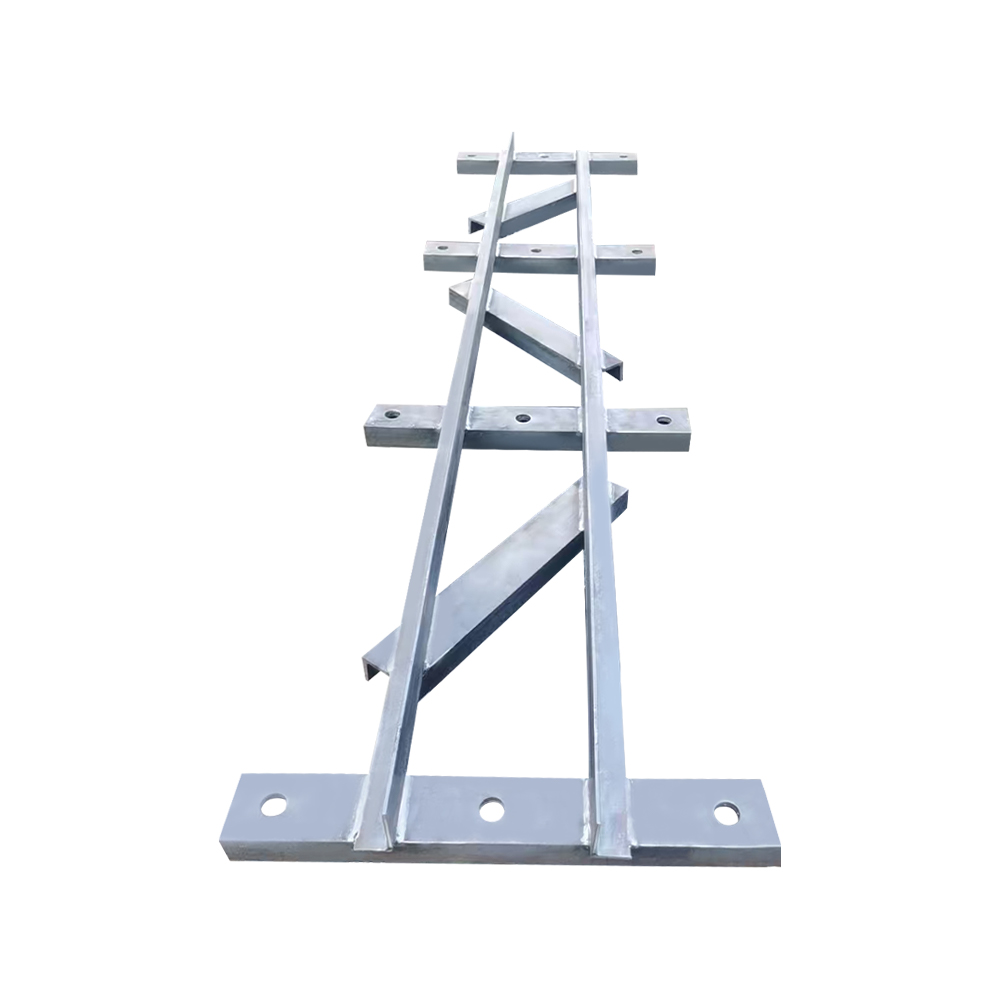
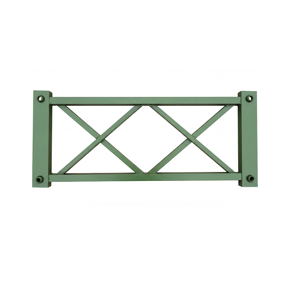
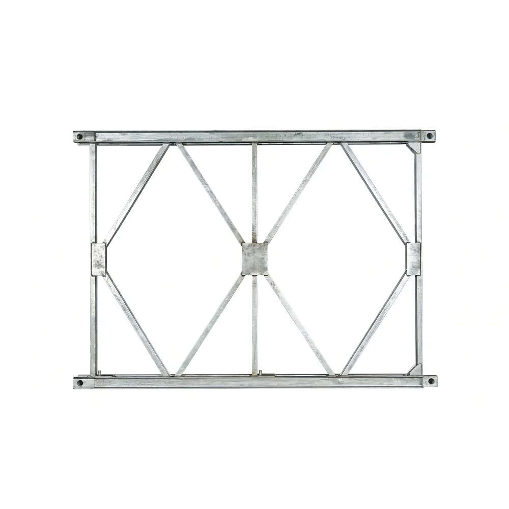
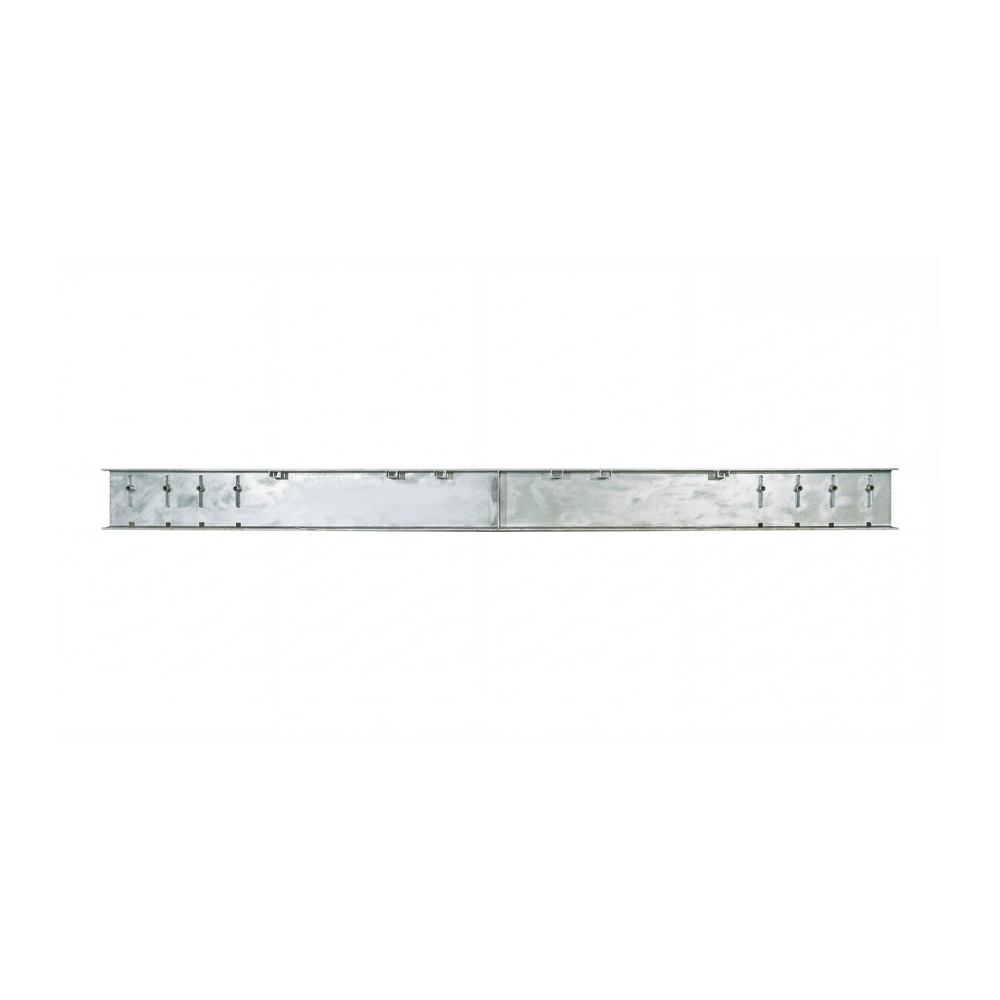
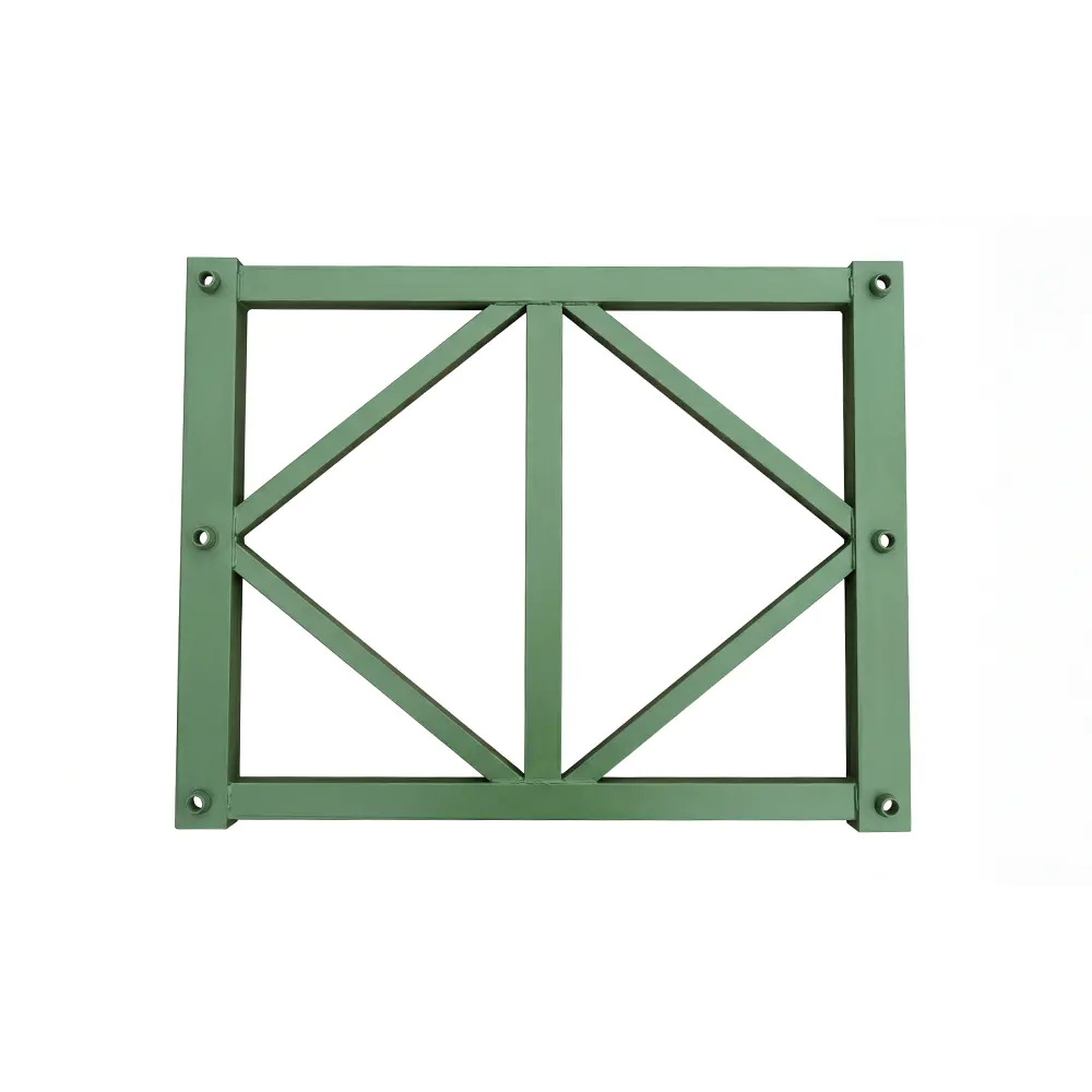
The HD200 Vertical Support Frame is a critical structural component for modern Bailey bridge systems, heavy-duty prefabricated truss structures, large formwork support assemblies, and emergency engineering projects. Designed to work with HD200 or Type 200 Bailey truss sections, this frame provides vertical load transfer, lateral restraint, and overall structural stability. It is not an isolated steel accessory; it is part of a complete load-bearing system that connects the truss, strengthening chords, horizontal support frames, deck structure, and foundation.
In temporary and semi-permanent bridge construction, the ability to assemble a reliable load-bearing structure quickly is essential. Contractors and project owners must often work under difficult conditions, including restricted construction windows, limited access to heavy equipment, unstable ground, emergency traffic requirements, or the need to maintain an existing transportation route. The HD200 Vertical Support Frame addresses these challenges by providing a standardized, high-strength vertical member that can be integrated into modular steel bridge systems with predictable dimensions and repeatable connections.
Its principal function is to transfer vertical forces from the upper parts of the bridge or support structure toward the foundation while helping prevent excessive deformation and overturning. When used together with horizontal support frames and strengthening chords, it creates a three-dimensional load-bearing arrangement. This arrangement helps distribute concentrated loads, control the height-to-width ratio of the assembled structure, and maintain stability during construction and service.
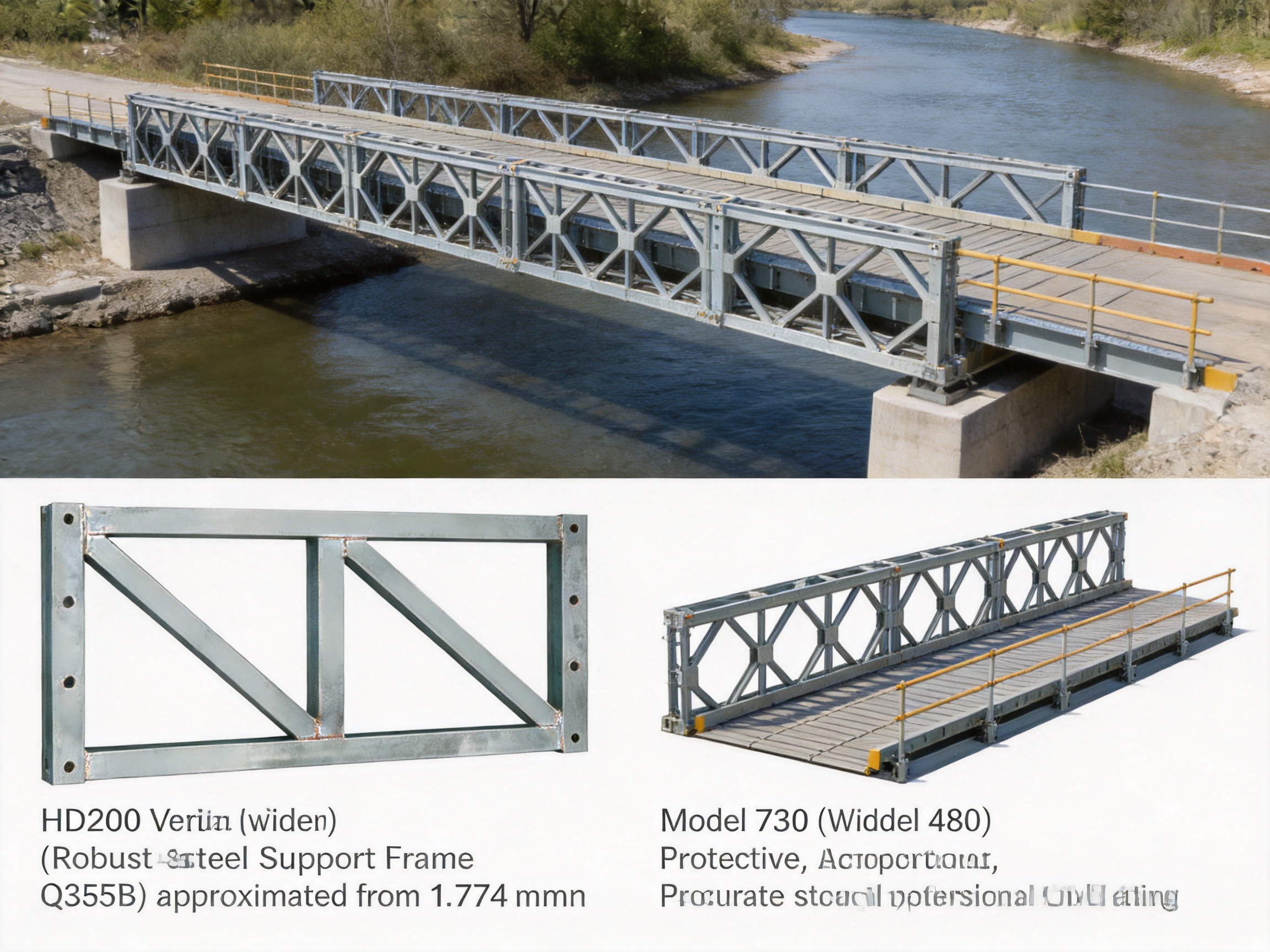
The product is available in two main specifications: Model 730 and Model 480. These models correspond to different HD200 truss spacing requirements. Both versions are manufactured from Q355B structural steel and use standardized dimensions suitable for modular bridge and support applications. With an external height of 1,774 millimeters and a plate thickness of 50 millimeters, the frames provide a substantial vertical load path while remaining suitable for prefabricated assembly and transport.
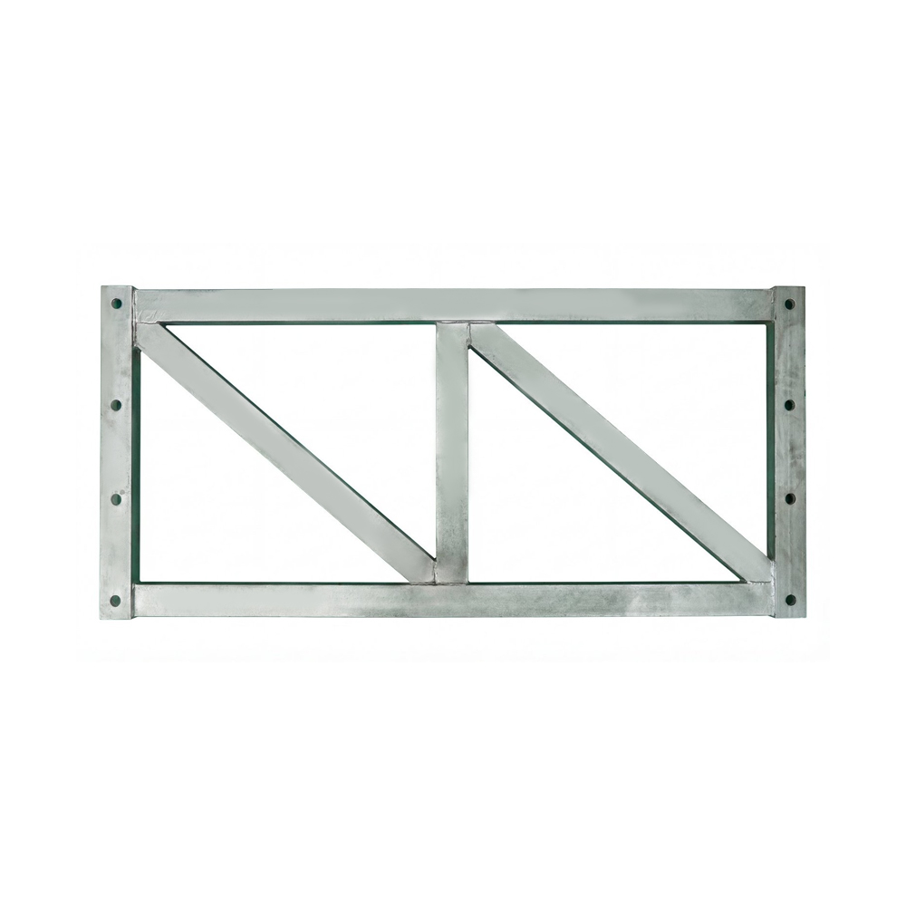
Type HD200 - Vertical Support Frame For Bailey Bridge
1. The Role of a Vertical Support Frame in an HD200 Bridge System
A modular steel bridge is designed as an interconnected structural system. Each component has a defined mechanical function, and the performance of the completed bridge depends on the cooperation of all major members. The truss sections resist bending and carry longitudinal forces. Deck components distribute traffic loads. Transverse members maintain spacing and transfer loads between trusses. Strengthening chords increase resistance to bending and compression. The vertical support frame ties these elements together and helps maintain the required geometry.
The HD200 Vertical Support Frame primarily carries and transfers vertical forces. These forces may originate from vehicles, pedestrians, construction equipment, deck assemblies, wind effects, temporary erection loads, or self-weight. The frame transmits the accumulated forces through the appropriate structural members and ultimately into the bearings, piers, abutments, or temporary foundations.
In a bridge system with a large span or a high load requirement, vertical stability becomes especially important. A truss can have sufficient theoretical strength but still experience unacceptable deflection, distortion, or instability if the supporting geometry is not controlled. The vertical support frame helps maintain the relative position of the truss components and reduces the possibility of local or overall deformation.
The component also helps resist overturning tendencies. A bridge or temporary support assembly can be affected by eccentric traffic loads, wind, construction activities, uneven settlement, and unbalanced erection stages. By connecting vertical and horizontal structural elements, the frame improves the continuity of the support arrangement. It contributes to a closed force-bearing loop in which loads can be distributed rather than concentrated in a single member or connection.
For this reason, the vertical support frame should be selected, installed, and inspected as part of the complete HD200 structural design. Its performance depends on correct matching with truss spacing, proper connection hardware, suitable foundation conditions, and compliance with the design loads and erection sequence.
2. Main Product Characteristics
2.1 Two Specifications for Different Truss Spacing
The HD200 Vertical Support Frame is supplied in Model 730 and Model 480 configurations. The two versions are intended to match the corresponding spacing arrangements of HD200 truss systems. Correct model selection ensures that the frame aligns properly with the truss geometry and that the connecting members can be installed without forced adjustment or field modification.
Model 730 has an external dimension of approximately 1,774 by 820 by 50 millimeters. Model 480 has an external dimension of approximately 1,774 by 570 by 50 millimeters. The difference in width allows the component to suit different system configurations while retaining the same basic vertical height and plate thickness.
The center-distance arrangement is approximately 1,694 by 250 plus 230 plus 250 millimeters. These dimensions provide a reference for engineering layout, connection planning, and compatibility checks. Before ordering, project engineers should confirm the required model against the actual HD200 truss arrangement, deck configuration, support spacing, and structural calculations.
2.2 Q355B Structural Steel
The frame is manufactured from Q355B steel, a commonly used high-strength structural steel grade for demanding fabricated steel applications. Compared with ordinary mild structural steel, Q355B provides a higher yield strength level and is suitable for components that must resist significant axial, bending, and connection-related forces.
Material selection is important for modular bridge components because they may be exposed to repeated loading, transportation impacts, changing weather conditions, erection stresses, and long periods of outdoor service. A suitable structural steel grade provides a practical balance between strength, weldability, fabrication efficiency, and availability.
The use of Q355B also supports standardized production and engineering documentation. Material certificates, inspection records, welding records, and dimensional reports can be associated with each production batch or shipment. This traceability is valuable for contractors and project owners who need to verify the quality of structural materials before installation.
2.3 Robust 50-Millimeter Plate Thickness
The specified plate thickness of 50 millimeters gives the frame a substantial structural section. A thick fabricated plate arrangement can improve resistance to local buckling, connection distortion, impact during handling, and concentrated force transfer. It also provides a durable base for welded stiffeners, connection plates, and other structural details used in the completed assembly.
However, plate thickness alone does not determine the capacity of a structural component. The final performance depends on the steel grade, cross-sectional configuration, weld quality, connection design, unsupported length, bracing arrangement, load eccentricity, and foundation conditions. The HD200 Vertical Support Frame is therefore intended to be used according to an approved structural design rather than as an independent substitute for engineering calculations.
2.4 Compatibility with Modular Construction
Modular bridge systems are valued for their standardized and interchangeable components. A properly manufactured vertical support frame can be transported to the project site, positioned according to the erection drawings, and connected with other prefabricated members. This reduces the need for extensive cutting, drilling, or welding in the field.
Factory production also supports consistent dimensions between different batches. Consistency is especially important when several frames are installed along a bridge or support system. Uniform components help maintain alignment, simplify the erection sequence, reduce adjustment work, and improve the predictability of the completed structure.
3. Structural Advantages in Comparison with Conventional Alternatives
3.1 Better Load Organization
One of the main advantages of the HD200 Vertical Support Frame is its ability to organize loads within a complete three-dimensional system. Conventional improvised supports may rely on individual steel posts, temporary bracing, or locally fabricated frames. These solutions can work in limited situations, but they may lack consistent connection geometry and may make load paths difficult to verify.
The HD200 frame is designed for integration with a specific family of truss and support components. Its dimensions, spacing, and connection locations are coordinated with the HD200 system. This makes it easier for engineers to establish a clear load path from the deck or upper structure through the truss and support assembly to the foundation.
A clear load path helps reduce uncertainty during both design and construction. It also makes inspection more practical because the position of each component can be compared with the approved drawings and installation tolerances.
3.2 Improved Stability for Large-Span and High-Load Structures
The frame is suitable for engineering scenarios involving spans from approximately 9.144 to 60.96 meters and loading requirements associated with HS25 class and above, subject to the project design. These span and load ranges indicate the type of heavy-duty application for which the HD200 system may be considered.
Large-span temporary bridges experience greater bending effects, deflection sensitivity, and erection-stage instability than short-span structures. As the span increases, the importance of maintaining the correct distance between trusses and controlling lateral movement also increases. The vertical support frame contributes to this control by linking the upper and lower elements of the support system.
For high-load applications, the component supports the distribution of forces into the foundation. This can help avoid excessive demand on individual members and reduce the risk of local deformation. The actual capacity must still be confirmed by design calculations that account for span, traffic loading, impact factors, wind, seismic conditions where applicable, foundation settlement, and construction-stage effects.
3.3 Reduced Field Fabrication
Improvised structural supports often require on-site measurement, cutting, drilling, and welding. Such work can increase labor requirements and introduce inconsistencies between different locations. It may also be difficult to control welding conditions in rain, wind, confined spaces, or remote project environments.
A prefabricated HD200 Vertical Support Frame arrives at the site with the main fabrication work completed. The contractor can focus on lifting, positioning, bolting, alignment, and inspection. Reducing field fabrication can shorten the installation period and make the construction process more repeatable.
Less field modification also preserves the integrity of the original engineering design. When a component is altered without formal review, its strength, stiffness, and connection performance may no longer match the design assumptions. Standardized prefabricated components help minimize this risk.
3.4 Efficient Transportation and Reuse
Bailey bridge components are commonly selected for projects where rapid deployment, relocation, or future reuse is important. The HD200 Vertical Support Frame supports this modular philosophy. It can be manufactured, delivered, erected, dismantled, and stored as part of a reusable structural inventory, provided that inspection confirms its condition after each project.
Reusable components can lower the total lifecycle cost of temporary bridges and support systems. Instead of fabricating a new support assembly for every project, contractors can maintain a controlled stock of standardized frames and compatible HD200 members. This is particularly useful for emergency response organizations, infrastructure contractors, bridge rental companies, and public works departments.
3.5 Adaptability to Different Engineering Applications
The vertical support frame is not limited to one bridge arrangement. In addition to Bailey bridges, it can be applied in heavy-duty truss systems, large formwork support structures, temporary access systems, and emergency rescue projects. Its adaptability makes it useful where a strong, modular, and quickly assembled vertical support element is required.
Large formwork systems, for example, may require vertical support members capable of carrying substantial concrete pressure, formwork weight, working platforms, and construction equipment. When appropriately designed and braced, HD200-related components can contribute to these support arrangements. The project engineer must verify the formwork loads and connection details separately because bridge loading assumptions are not automatically applicable to formwork systems.
4. Manufacturing Process and Quality Control
The performance of a heavy-duty steel support frame depends not only on its design but also on the quality of its manufacture. A frame with correct nominal dimensions may still perform poorly if the steel is unsuitable, welds are defective, connection plates are misaligned, or excessive distortion is left uncorrected. Advanced fabrication practices are therefore essential for structural reliability.
4.1 Engineering Review and Production Planning
Manufacturing begins with the review of engineering drawings, material specifications, dimensional requirements, welding details, and inspection criteria. The production team must confirm the selected model, whether Model 730 or Model 480, before material cutting begins.
Production planning should include a clear sequence for cutting, forming, assembly, welding, correction, surface treatment, inspection, marking, and packing. A controlled sequence reduces dimensional accumulation and ensures that critical connection locations remain within the required tolerance.
When the frame is part of a larger bridge order, production planning also considers the number of frames, truss sections, strengthening chords, horizontal support frames, deck components, bolts, and accessories required for the complete project. Coordinated production and packing reduce the risk of missing components during site erection.
4.2 Material Verification
Q355B steel should be verified against the applicable purchase specification before fabrication. Material inspection may include checking the mill certificate, heat number, thickness, surface condition, and chemical or mechanical properties where required by the project quality plan.
Each batch of steel should remain identifiable during cutting and assembly. Traceability allows the manufacturer to connect finished components with the source material and related inspection records. This is particularly important for bridge projects involving government authorities, international contractors, or formal third-party inspection.
4.3 Precision Cutting and Preparation
Steel plates and sections should be cut using suitable equipment and controlled procedures. Precision cutting improves the fit-up of the frame and helps maintain the designed external dimensions. Cut edges may require cleaning, grinding, or additional preparation before welding, depending on the connection detail.
Accurate preparation is important because small dimensional errors can accumulate when several components are assembled together. Misaligned plates can create unintended eccentricity, gaps, residual stress, and difficulty during bolt installation. A controlled cutting and preparation process helps ensure that the final frame matches the HD200 system geometry.
4.4 Controlled Assembly and Welding
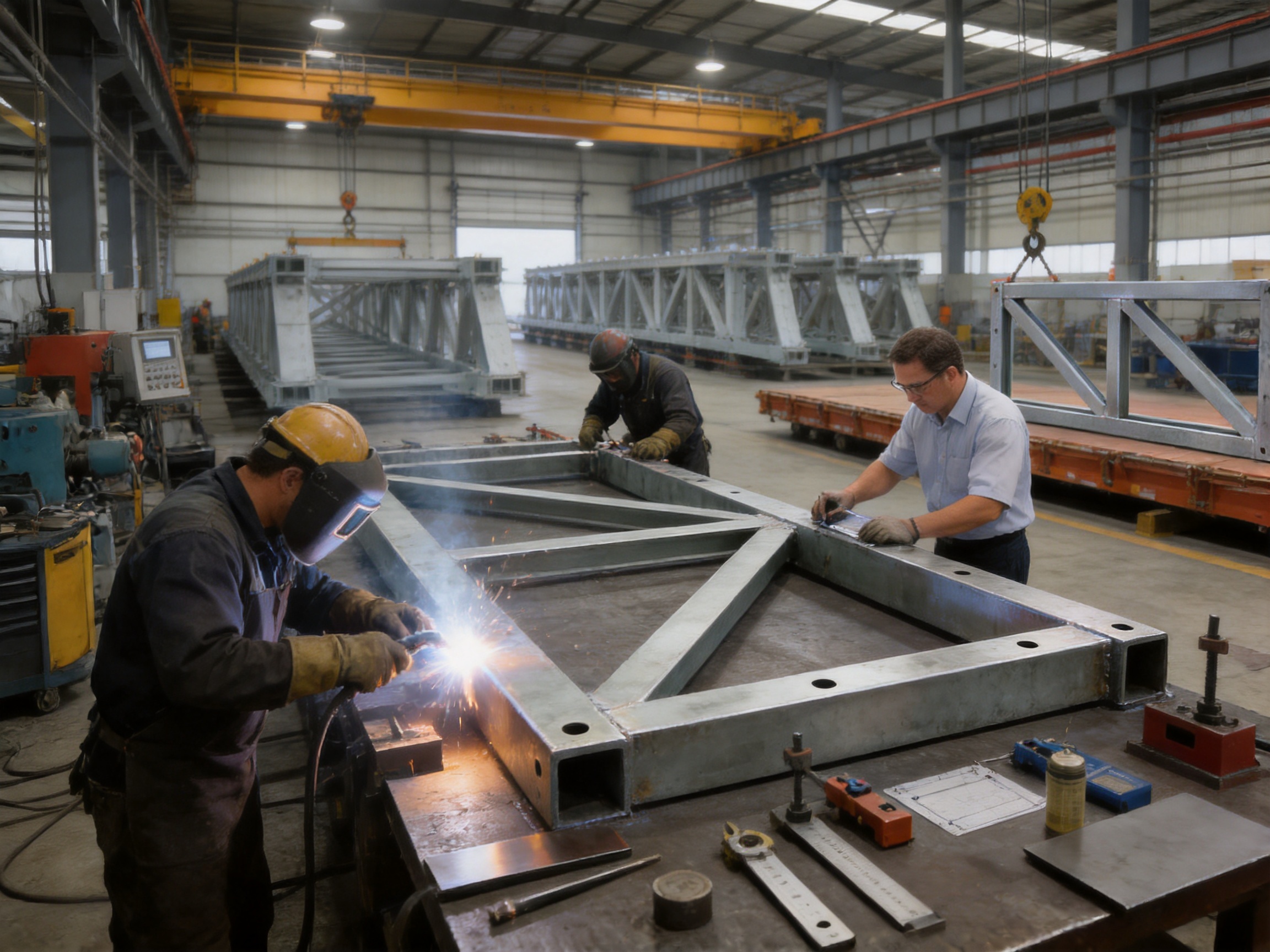
During assembly, components are positioned in fixtures or on calibrated work surfaces. Temporary clamps, tack welds, and positioning tools hold the parts in place before permanent welding. Proper fit-up helps control gaps and alignment while reducing the need for correction after welding.
Welding procedures should be selected according to the Q355B material, plate thickness, joint type, structural requirements, and applicable standards. Welding operators should be qualified for the relevant process. Preheating, interpass temperature control, welding sequence, and cooling conditions may be controlled to reduce cracking and distortion.
The welding sequence is especially important for a thick fabricated frame. If welds are deposited unevenly, heat can cause the component to deform or twist. Symmetrical welding, balanced heat input, suitable restraint, and controlled sequencing help maintain the intended geometry.
Visual inspection is normally carried out throughout the process. Depending on the project requirements, non-destructive testing may also be used for selected welds. Possible methods include ultrasonic, magnetic particle, or other appropriate examinations. The inspection method should be determined by the joint category, design requirements, and applicable quality standards.
4.5 Dimensional Inspection and Correction
After welding, the frame should be inspected for external dimensions, center distances, squareness, flatness, connection alignment, weld appearance, and surface defects. The main dimensional references include the 1,774-millimeter external height, the model-specific width, the 50-millimeter plate thickness, and the specified center-distance arrangement.
Measured results should be recorded in an inspection report. If distortion is identified, correction should be carried out using approved methods. Controlled mechanical straightening or carefully managed thermal correction may be considered, depending on the extent and location of the distortion. Uncontrolled heating or excessive force should be avoided because it may affect the material or introduce additional residual stress.
4.6 Surface Protection
Steel bridge components may be exposed to rain, humidity, dust, deicing substances, construction chemicals, and marine or industrial environments. Surface preparation and protective coating therefore have an important role in service life.
A typical protection process may include removal of oil, rust, scale, and welding residue, followed by abrasive preparation or another specified cleaning method. The coating system can then be selected according to the project environment, expected service period, maintenance plan, and customer requirements.
For temporary bridges that will be dismantled and reused, coating durability remains important because repeated handling can damage exposed surfaces. Touch-up procedures should be defined for lifting points, bolt areas, edges, and locations affected during transportation or erection.
4.7 Identification, Packing, and Delivery
Each frame should be marked with its model, identification number, production information, and any required orientation or lifting information. Clear markings help prevent the wrong model from being installed and simplify inventory control after dismantling.
During packing, frames should be protected against impact, uncontrolled movement, and water accumulation. Packing should also support efficient unloading and lifting at the project site. When the order includes a complete bridge system, the manufacturer can organize components according to erection stages or shipment groups.
5. Company Manufacturing and Engineering Strengths
The product is manufactured and supplied by Zhenjiang Jinhao Road & Bridge Supporting Engineering Co., Ltd., a Chinese enterprise specializing in Bailey bridges, bridge launching gantry systems, hanging baskets, pier formwork, bridge steel formwork, and related engineered steel structures.
Established in 2017, the company has developed from a business focused on construction and industrial materials into an integrated organization involved in design, manufacturing, erection, and leasing. This broader experience is important because bridge components are most effective when their manufacturing details are informed by actual site conditions and erection requirements.
5.1 Integrated Design and Fabrication Capability
An integrated design and fabrication approach allows the supplier to consider the complete structural system rather than treating the vertical support frame as an isolated product. The company can support planning for truss arrangements, bridge spans, support conditions, erection sequences, and related steel components.
This system-oriented capability can help contractors reduce coordination problems. Instead of purchasing incompatible components from multiple sources, a project team may obtain the HD200 truss sections, vertical support frames, horizontal support frames, strengthening chords, bridge decking, and other related products through a coordinated supply arrangement.
5.2 Experience with Modular Steel Structures
The company’s product range includes Type 321 Bailey truss sections, HD200 or Type 200 Bailey truss sections, triangular and diamond hanging baskets, bridge steel formwork, and launching equipment. This product coverage demonstrates familiarity with modular steel construction, temporary works, bridge erection, and heavy structural fabrication.
Experience with different steel systems also supports practical problem solving. A bridge project may require temporary access, a launching arrangement, a support tower, a formwork structure, or a combination of several systems. A manufacturer with a broad product portfolio can better understand how these components interact during construction.
5.3 Support for Customized Projects
Although the HD200 Vertical Support Frame is based on standardized dimensions, projects may differ in span, loading, foundation type, environmental conditions, transport restrictions, and erection method. The company provides customized fabrication, design assistance, system planning, technical support, and quality management for project-specific requirements.
Customization should not mean uncontrolled alteration of a standard component. Instead, it should be based on engineering review, documented drawings, approved materials, and controlled production. This approach preserves the benefits of modular standardization while allowing the system to respond to real project conditions.
5.4 Manufacturing Location and Logistics
The company operates in Shangdang Town Industrial Park in Dantu District, Zhenjiang City, Jiangsu Province. The location provides access to regional transportation routes and industrial supply chains. Its proximity to major road, canal, and railway infrastructure can support the movement of large steel components to domestic and international customers.
Efficient logistics are particularly valuable for emergency bridge and temporary works projects. When a bridge is needed after flooding, a natural disaster, infrastructure failure, or urgent construction activity, delivery planning can be as important as fabrication capacity. Proper packing, shipment coordination, and documentation help reduce delays after the components leave the factory.
6. Engineering Applications
6.1 Temporary and Emergency Bridges
The HD200 Vertical Support Frame is suitable for temporary and emergency bridge systems where speed, strength, and modularity are required. Emergency applications may include replacement access after a bridge failure, temporary crossings during rehabilitation, flood response, disaster recovery, and construction access to isolated work areas.
In these situations, a standardized vertical frame can help the construction team establish a stable support arrangement quickly. The frame works with HD200 trusses and related components to create a bridge that can later be dismantled or adapted when the permanent infrastructure is completed.
6.2 Semi-Permanent Transportation Routes
Some projects require a bridge to remain in service for an extended period while a permanent structure is designed, financed, or constructed. A semi-permanent HD200 bridge may provide a practical transportation route for vehicles, pedestrians, or construction traffic when designed and maintained correctly.
Longer service periods require closer attention to corrosion protection, inspection access, drainage, traffic management, fatigue considerations, foundation performance, and periodic tightening or replacement of connection components. The vertical support frame contributes to the structural system, but the complete bridge must be assessed as a whole.
6.3 Construction Access and Site Logistics
Large infrastructure projects often need temporary access routes for cranes, concrete trucks, excavators, and material deliveries. A heavy-duty modular bridge can allow construction traffic to cross rivers, drainage channels, rail corridors, roads, or excavations without waiting for the permanent bridge to be completed.
The support frame helps maintain the required bridge geometry under construction loads. It is especially useful where the temporary route must carry heavier equipment or where a simple light-duty truss is not sufficient.
6.4 Formwork and Temporary Support Systems
In bridge construction, formwork and falsework must support concrete, reinforcement, working platforms, construction equipment, and dynamic site activities. The HD200 Vertical Support Frame can be incorporated into large formwork support systems where its dimensions and capacity meet the project design requirements.
Such use requires an independent temporary works assessment. Concrete placement can create rapidly changing loads, and formwork may be vulnerable to uneven loading, construction impact, vibration, and settlement. Proper horizontal bracing, foundation preparation, and erection monitoring are essential.
6.5 Bridge Erection and Launching Arrangements
Bailey components can also be used in bridge erection systems, guide beams, tower columns, gantry hangers, and related temporary structures. A vertical support frame may form part of a support tower or erection arrangement that assists in positioning bridge sections across an obstacle.
Launching and erection stages can generate force conditions different from those encountered during normal service. The design should therefore consider lifting points, temporary reactions, unbalanced loads, wind during launching, equipment movement, and stage-by-stage stability.
7. Technical Data
Product |
HD200 Vertical Support Frame for Bailey Bridge |
System |
HD200 or Type 200 Bailey Truss Section System |
Model 730 External Dimensions |
1,774 × 820 × 50 millimeters |
Model 480 External Dimensions |
1,774 × 570 × 50 millimeters |
Center-Distance Dimensions |
1,694 × (250 + 230 + 250) millimeters |
Primary Material |
Q355B structural steel |
Primary Function |
Vertical load transfer, structural restraint, and stability support |
Typical Applications |
Bailey bridges, heavy-duty trusses, formwork supports, emergency works, and temporary structures |
Related Components |
HD200 truss sections, horizontal support frames, strengthening chords, decking, and connection hardware |
The dimensions shown above are product reference data. Final selection should be based on the approved project drawings, design load requirements, truss spacing, support arrangement, and applicable technical standards. Customers should confirm whether additional coating, inspection, documentation, connection hardware, or customized fabrication is required before production.
8. Installation and Site Management Considerations
8.1 Foundation and Bearing Conditions
A strong steel frame cannot compensate for an inadequate foundation. Before erection, the project team should verify the bearing capacity, level, settlement risk, drainage, and overall stability of the supporting ground or foundation. Temporary works may require concrete pads, steel grillages, pile-supported foundations, or other engineered arrangements.
The foundation should provide a level and stable interface for the vertical support frame and associated bridge components. Uneven settlement can introduce unintended forces, reduce clearance, distort the truss, and increase stress in connections. Monitoring may be required during erection and service, particularly on soft ground or in areas affected by water movement.
8.2 Correct Model Selection
Model 730 and Model 480 should not be treated as interchangeable without engineering confirmation. Their widths correspond to different HD200 truss spacing arrangements. Installing the wrong model may cause misalignment, connection difficulty, or an unintended load path.
Before delivery, the contractor should compare the frame identification markings with the erection drawings and packing list. During installation, the orientation and center distances should be checked before final tightening of the connections.
8.3 Alignment and Bracing
Vertical support frames should be positioned accurately and connected to the designated horizontal support frames, truss sections, and strengthening chords. Temporary bracing may be needed before the complete system becomes stable.
Alignment checks should consider verticality, longitudinal position, transverse spacing, elevation, and connection-hole matching. Any significant deviation should be reviewed by the responsible engineer rather than corrected through uncontrolled force or field cutting.
8.4 Lifting and Handling
Safe lifting procedures are necessary because the frame is a heavy fabricated steel component. Lifting points, slings, shackles, cranes, and temporary supports should be selected according to the component weight and center of gravity. Workers should remain outside suspended-load zones, and the frame should not be dragged in a manner that could damage edges or connection plates.
After unloading, components should be stored on stable supports above standing water and protected from contamination. Identification marks should remain visible throughout storage and installation.
8.5 Inspection After Installation
Following erection, the project team should inspect the frame for cracks, coating damage, distorted plates, incomplete connections, loose bolts, weld defects, and contact problems. The inspection should also confirm that the surrounding truss, horizontal frames, strengthening chords, deck, and support points are correctly installed.
For bridges placed into service, regular inspections should be scheduled according to the traffic level, environmental exposure, service duration, and local regulations. Particular attention should be paid to connection areas, bearing locations, drainage points, impact-prone surfaces, and regions where corrosion may accumulate.
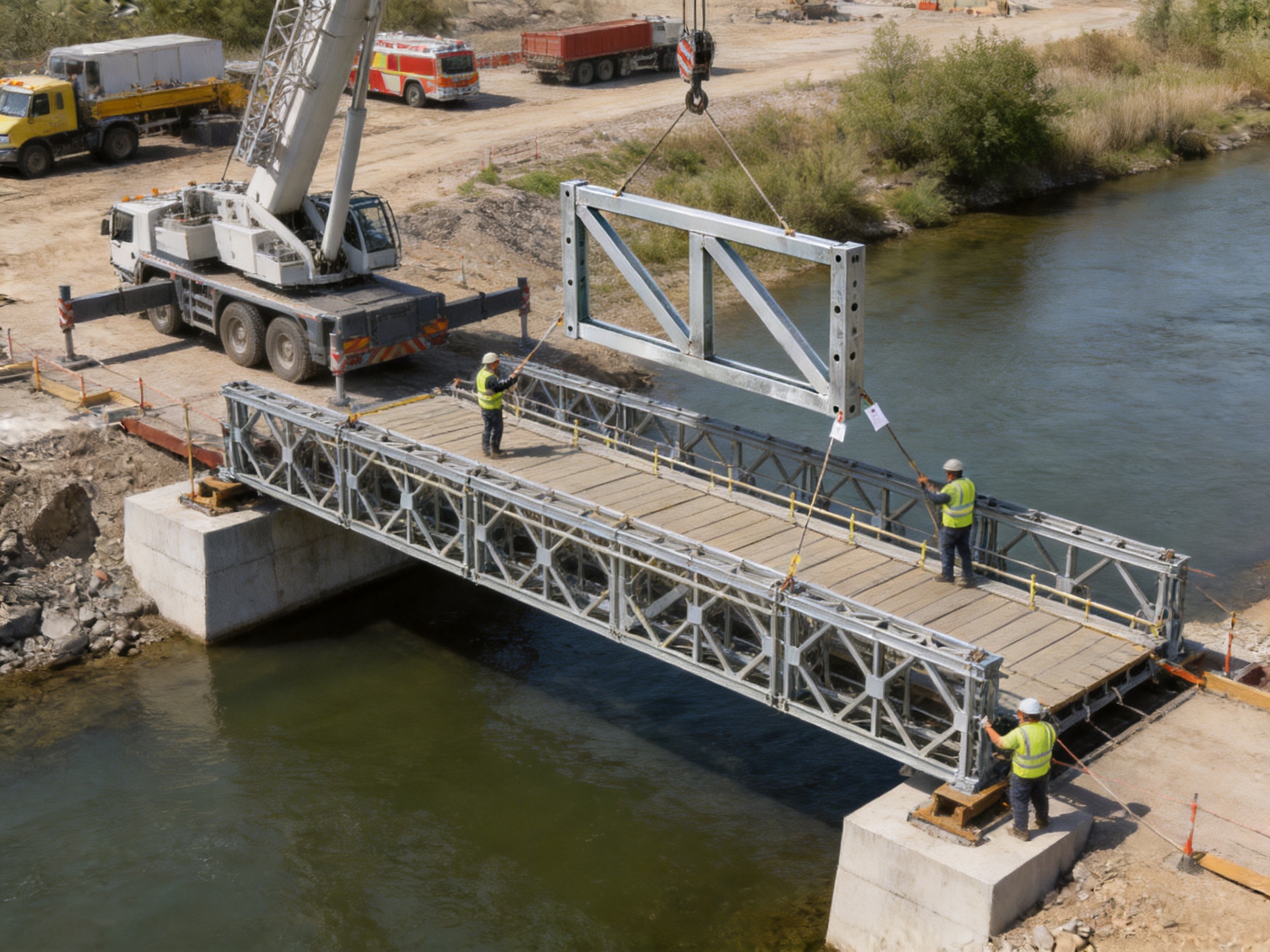
9. Why Factory-Produced Components Offer Greater Project Value
Factory-produced structural components provide several advantages over site-built alternatives. First, the manufacturing environment allows better control of materials, equipment, welding conditions, dimensional inspection, and documentation. Second, production can be organized around repeatable fixtures and procedures, which improves consistency when many identical frames are required.
Third, factory production separates major steelwork from the most difficult site conditions. Welding and cutting can be completed in a controlled environment rather than on an exposed bridge deck, temporary platform, or remote construction site. This can improve productivity and reduce the risk of weather-related delays.
Fourth, prefabrication makes quality problems easier to identify before shipment. A frame can be measured, inspected, marked, and corrected at the factory. Discovering dimensional or connection problems before delivery is generally less disruptive than discovering them after a crane and erection crew are already mobilized.
Finally, standardized production supports lifecycle management. When frames are clearly identified and inspection records are maintained, contractors can track their use, condition, repairs, coating history, and suitability for future projects.
10. Procurement Guidance for Contractors and Project Owners
When purchasing HD200 Vertical Support Frames, buyers should provide more than a simple quantity request. The supplier should receive the intended application, span, design loading, bridge width, truss arrangement, foundation conditions, environmental exposure, erection method, and required delivery schedule.
The buyer should confirm whether the order includes only the vertical support frames or a complete HD200 bridge system. A complete system may require truss panels, pins, bolts, transoms, deck units, strengthening chords, horizontal frames, bracing, bearings, ramps, handrails, and other accessories.
Quality documentation should be discussed before manufacturing begins. Depending on the project, required documents may include material certificates, welding procedure records, operator qualifications, dimensional inspection reports, coating records, non-destructive testing reports, packing lists, installation drawings, and product identification records.
Customers should also ask about service support. For complicated bridge projects, design coordination and erection guidance can be as important as the steel components themselves. A supplier with experience in manufacturing, erection, and leasing can often provide practical recommendations related to assembly, transportation, component reuse, and maintenance.
For export projects, packaging and documentation should be prepared for international transportation. Component labeling, shipment grouping, lifting instructions, corrosion protection, and spare-part planning can reduce problems after arrival at the destination port or job site.
11. Sustainability and Reuse Benefits
Modular steel bridges can support more sustainable construction by allowing components to be reused across multiple projects. A reusable frame avoids the need to fabricate a completely new support member for every temporary crossing. At the end of a project, the frame can be inspected, repaired where necessary, recoated, and returned to inventory.
Steel is also a recyclable material. When a component eventually reaches the end of its usable structural life, the material can be recovered and processed through established recycling channels. Proper maintenance extends service life and reduces the consumption of new materials.
Reuse must be managed responsibly. Every dismantled component should be inspected for permanent deformation, fatigue damage, corrosion loss, weld cracking, enlarged holes, impact damage, and missing identification. Reuse should be approved only when the component continues to meet the requirements of the next project.
12. Q&A
Q1: What is the main purpose of the HD200 Vertical Support Frame?
Its main purpose is to transfer vertical loads and improve the stability of an HD200 Bailey bridge or heavy-duty truss system. It helps connect the truss, horizontal support frames, strengthening chords, and foundation into a coordinated three-dimensional structure.
Q2: What is the difference between Model 730 and Model 480?
The two models have different external widths and are intended for different HD200 truss spacing arrangements. Model 730 is approximately 1,774 × 820 × 50 millimeters, while Model 480 is approximately 1,774 × 570 × 50 millimeters. The correct model should be selected according to the project drawings and actual truss configuration.
Q3: What material is used to manufacture the frame?
The frame is manufactured from Q355B structural steel. This material is suitable for heavy-duty fabricated steel applications and provides a high-strength option for vertical load-bearing components. Material certification and project-specific requirements should be confirmed during procurement.
Q4: Can the frame be used independently?
No. The frame is intended to function as part of a complete HD200 structural system. Its capacity and stability depend on the truss sections, strengthening chords, horizontal support frames, connections, bracing, foundation, and design loading. It should be installed according to an approved engineering design.
Q5: Is the frame suitable for emergency bridge construction?
Yes. Its modular configuration and compatibility with HD200 Bailey bridge components make it suitable for emergency, temporary, construction-access, and semi-permanent bridge applications, subject to project design and site conditions.
Q6: Can it be used in large formwork support systems?
It may be incorporated into large formwork or temporary support systems when its dimensions, capacity, connections, and bracing satisfy the relevant design requirements. Formwork loading conditions differ from bridge traffic loading, so a separate temporary works assessment is required.
Q7: What span range can the HD200 system serve?
The product information identifies applications involving approximate spans from 9.144 to 60.96 meters. The actual usable span depends on the bridge arrangement, design load, truss configuration, support conditions, deflection limits, wind, erection method, and applicable standards.
Q8: What is the HS25 reference in the product information?
HS25 refers to a heavy highway loading classification used as an engineering reference for the intended application range. The final bridge design must verify the precise loading model, traffic conditions, impact factors, lane arrangement, and local code requirements.
Q9: What manufacturing inspections are important?
Important inspections may include material verification, dimensional measurement, weld visual inspection, non-destructive testing where specified, connection-hole and center-distance checks, surface preparation, coating thickness, marking, and final packing inspection.
Q10: Can the frames be reused?
Yes, modular steel frames are commonly designed with reuse in mind. Before reuse, each frame should be inspected for deformation, corrosion, cracks, connection damage, coating deterioration, and other defects. Reuse should be approved for the new project based on the inspection results and engineering requirements.
Q11: Does the manufacturer provide more than the steel frame?
The company’s capabilities include design, manufacturing, erection, leasing, customized fabrication, system planning, and technical support for Bailey bridges, launching gantries, hanging baskets, pier formwork, bridge steel formwork, and related structures. The available scope should be confirmed for each project.
Q12: What information should be supplied when requesting a quotation?
A quotation request should include the required model, quantity, bridge span, truss spacing, design load, intended application, delivery location, surface-treatment requirements, inspection documents, connection accessories, and desired delivery schedule. Drawings or a preliminary layout are helpful for accurate technical and commercial review.
13. Conclusion
The HD200 Vertical Support Frame is a purpose-designed vertical load-bearing component for HD200 Bailey bridges and heavy-duty modular steel structures. Manufactured from Q355B structural steel and offered in Model 730 and Model 480 configurations, it provides a standardized solution for transferring vertical forces, controlling structural geometry, and improving overall stability.
Its advantages are most evident when it is used as part of a complete engineered system. In combination with HD200 truss sections, horizontal support frames, strengthening chords, decking, bracing, and properly designed foundations, it helps form a stable and efficient load-bearing arrangement for temporary, emergency, semi-permanent, and construction-support applications.
Compared with improvised site-fabricated supports, a factory-produced frame offers more consistent dimensions, controlled welding, traceable materials, reduced field modification, easier inspection, and better potential for reuse. These benefits can improve construction efficiency and reduce uncertainty in projects where time, access, and reliability are important.
The manufacturer’s experience in Bailey bridges, launching gantries, hanging baskets, bridge formwork, and related steel structures further supports the product’s practical value. Its integrated capabilities in design, manufacturing, erection, leasing, customized fabrication, and technical assistance allow customers to obtain more than an individual component; they can receive coordinated support for a complete temporary or permanent engineering solution.
For contractors, governments, infrastructure owners, and engineering companies, the HD200 Vertical Support Frame is a strong option for projects that require modular construction, high load-bearing potential, rapid deployment, and adaptable structural support. Correct model selection, professional design, controlled erection, foundation verification, and regular inspection remain essential to achieving safe and reliable performance.
References
1. Product technical information for the HD200 Vertical Support Frame for Bailey Bridge, including dimensions, material grade, model classifications, and intended applications.
2. General engineering principles for modular steel bridges, temporary bridges, emergency bridges, and prefabricated truss systems.
3. Structural steel fabrication and welding quality-control practices for heavy-duty fabricated components.
4. Temporary works engineering guidance for bridge erection, falsework, formwork support, lifting, bracing, and foundation preparation.
5. Standard practices for inspection, maintenance, corrosion protection, and reuse of modular steel bridge components.
6. Technical information concerning Bailey bridge truss sections, HD200 bridge systems, strengthening chords, horizontal support frames, bridge decking, and related erection equipment.


 Français
 Español
 عربى