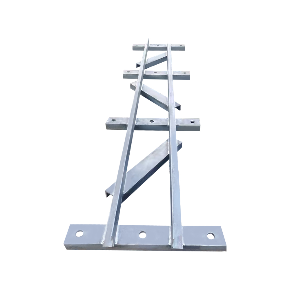
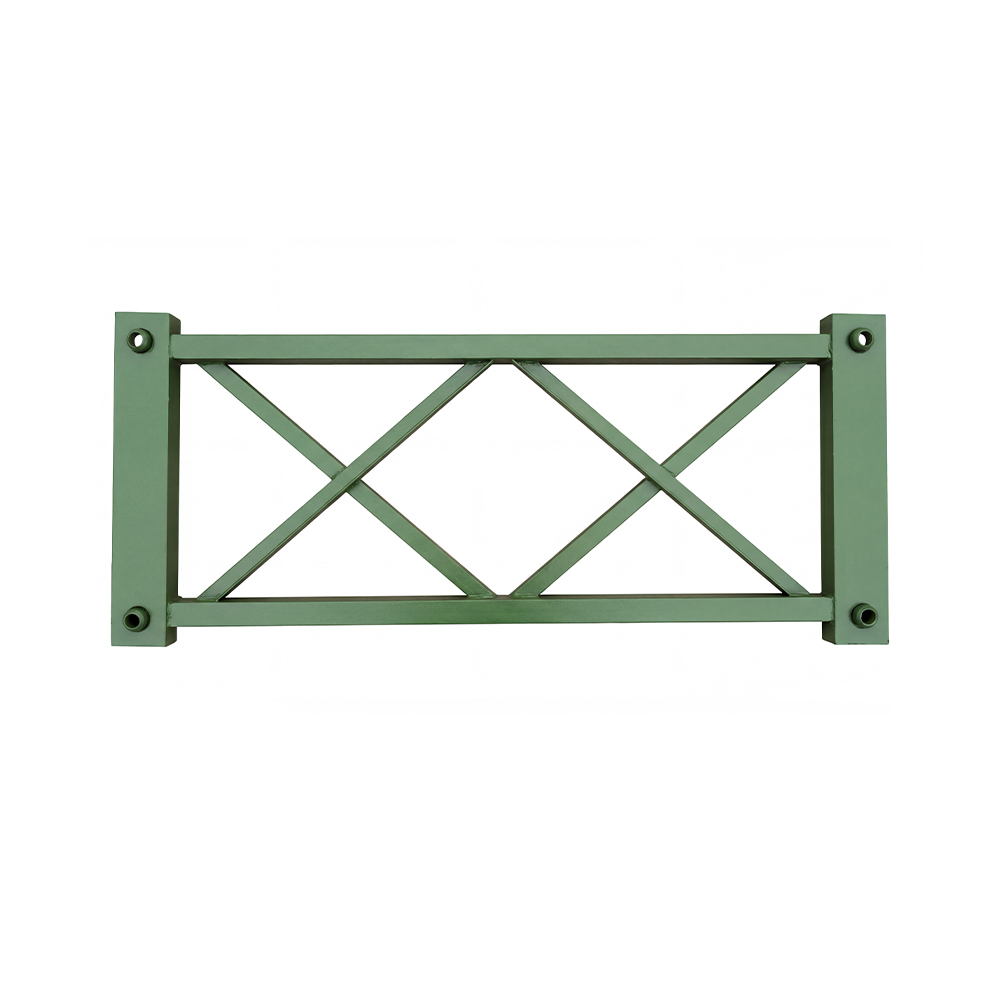
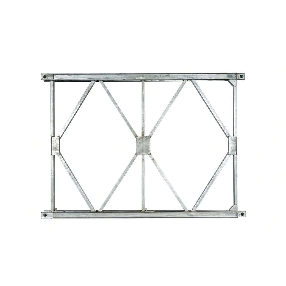
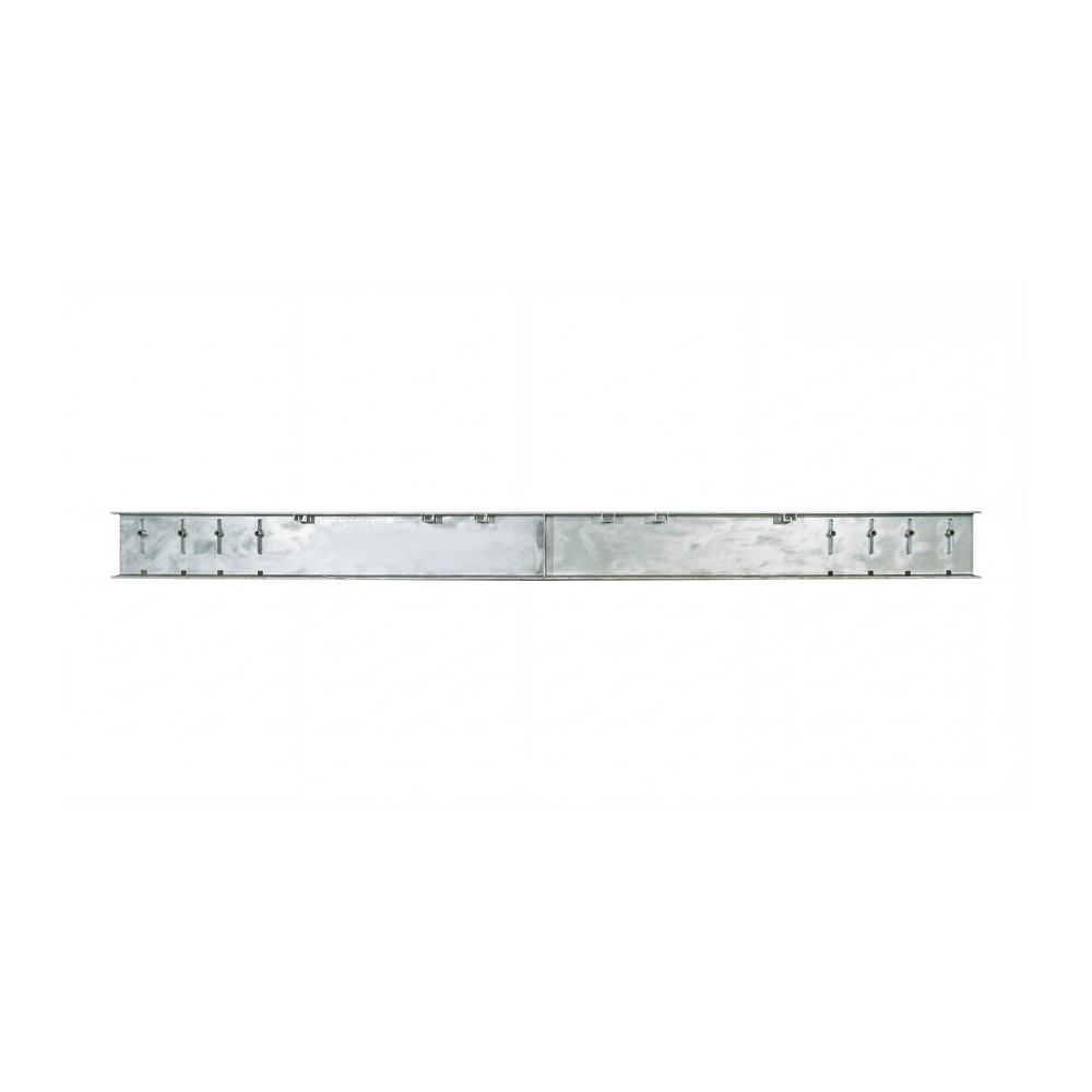
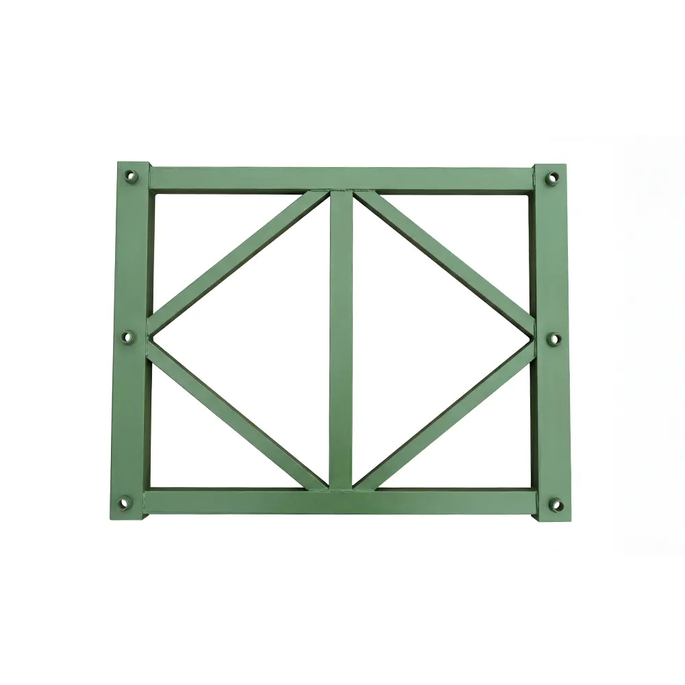
The HD200 Vertical Support Frame is a critical load-bearing component designed for HD200 prefabricated steel bridges and heavy-duty modular truss systems. Although compact compared with the complete bridge structure, this frame performs an essential structural function: it helps transfer vertical loads, limits deformation, supports the truss system, and contributes to the overall stability of the bridge assembly.
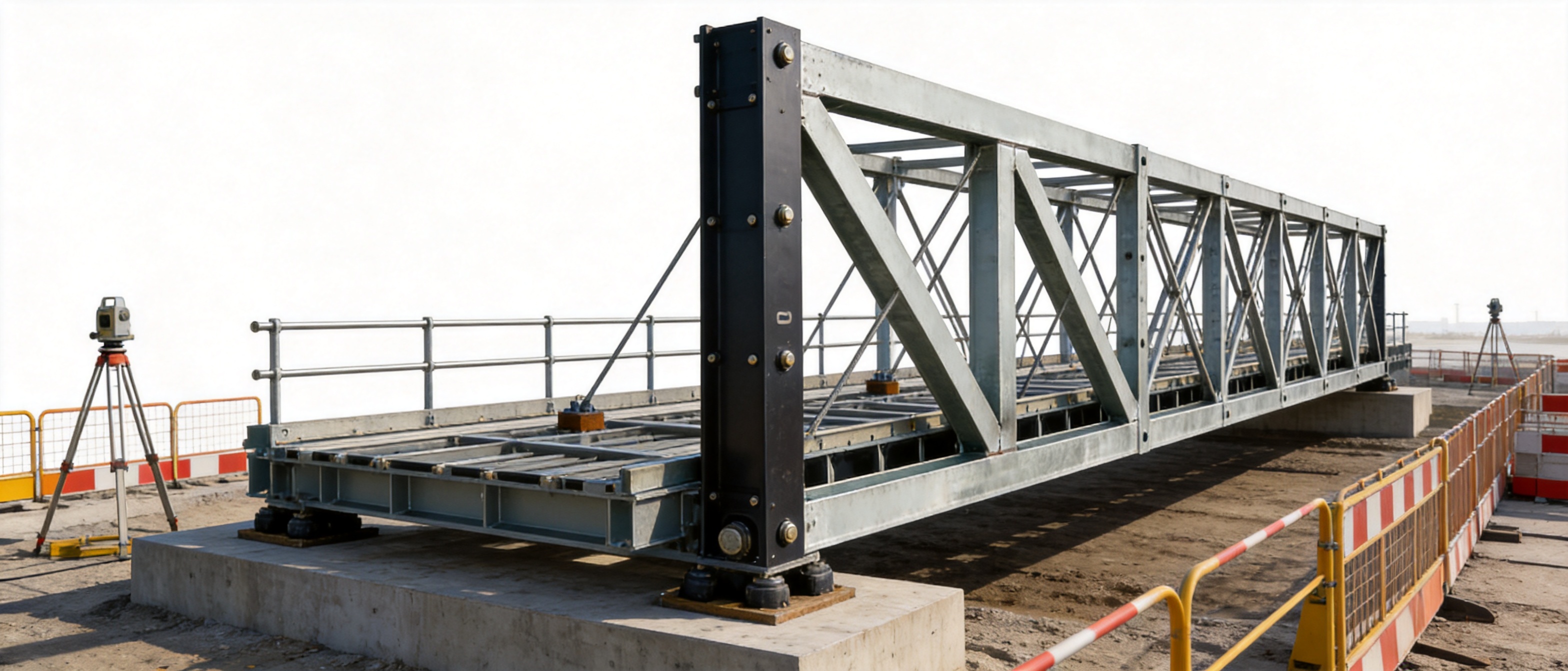
In a complete HD200 bridge system, the vertical support frame does not work as an isolated part. It forms a coordinated three-dimensional structure with the truss sections, horizontal support frames, strengthening chords, connection components, deck systems, and foundations. Together, these components create a stable force-bearing path from the bridge deck to the supporting foundation.
The HD200 Vertical Support Frame is available in 730 and 480 models. These two specifications correspond to the relevant HD200 truss spacing arrangements and allow engineers to select a suitable configuration for different bridge widths, support layouts, structural combinations, and project requirements. Manufactured from Q355B structural steel, the frame is intended for demanding bridge engineering, temporary and semi-permanent construction, heavy formwork support, emergency access, and other applications that require dependable steel structural performance.
This article explains the function, design characteristics, manufacturing advantages, installation considerations, engineering value, and practical applications of the HD200 Vertical Support Frame. It also examines why a professionally manufactured and properly coordinated support frame can offer advantages over ordinary fabricated frames or incompatible modular components.
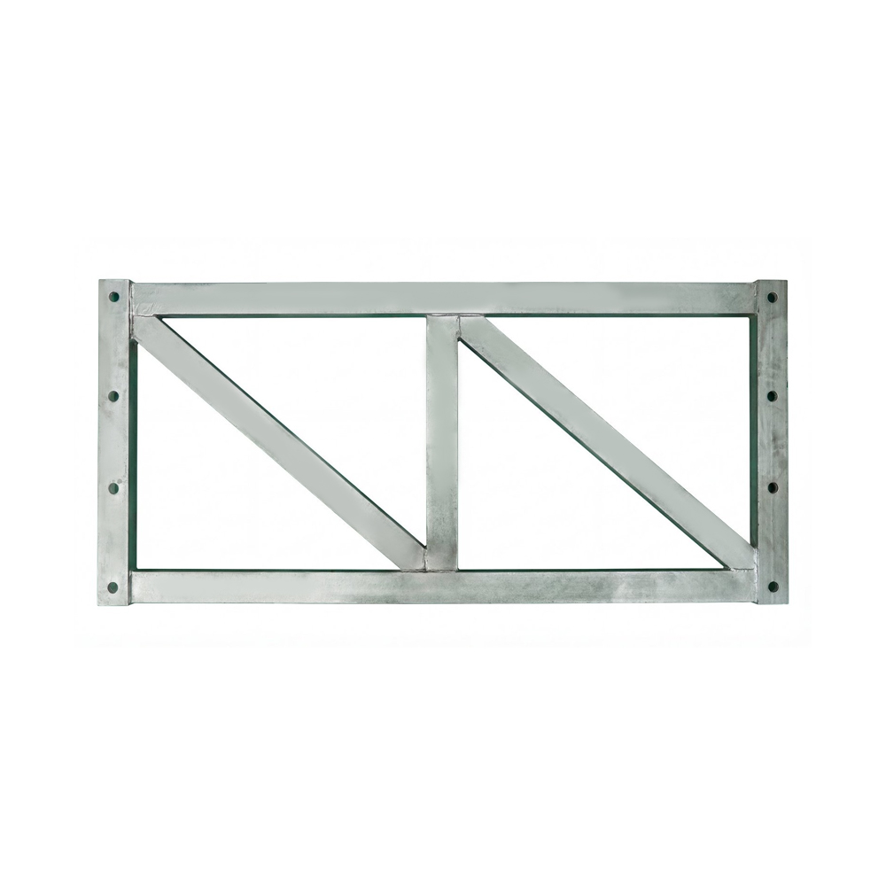
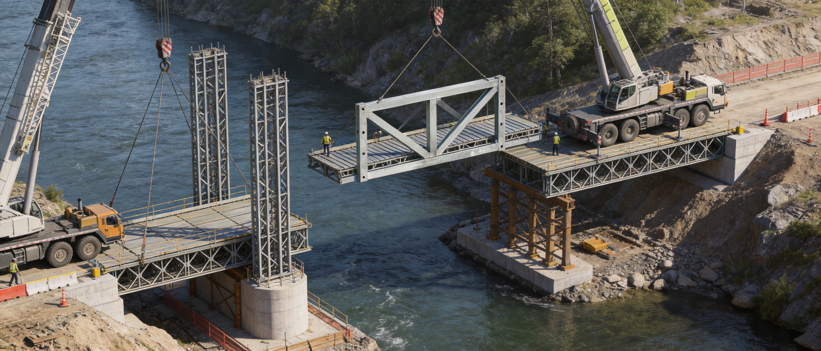
Type HD200 - Vertical Support Frame For Bailey Bridge
1. The Structural Role of a Vertical Support Frame
A prefabricated steel bridge must resist several types of forces during service and construction. These may include vehicle loads, pedestrian loads, self-weight, wind, impact effects, erection loads, temporary equipment loads, and dynamic effects caused by traffic or construction activities. The bridge system must transfer these forces safely and efficiently to the supports and foundation.
The vertical support frame is an important part of this load-transfer process. It helps maintain the vertical geometry of the truss arrangement while transferring forces between upper and lower structural components. It also contributes to the prevention of excessive vertical displacement, local instability, and unwanted movement between connected truss planes.
When used with horizontal support frames and strengthening chords, the vertical support frame helps transform a two-dimensional truss arrangement into a more stable three-dimensional structural system. This three-dimensional configuration improves the interaction between the different truss planes and supports the distribution of loads across the complete bridge width.
The frame is especially valuable in situations where the bridge or support system has a high height-to-width ratio, significant span, substantial design loading, or challenging foundation conditions. By helping establish a closed and coordinated force-bearing system, it supports the safe use of HD200 bridge components in large-span and heavy-duty engineering conditions.
1.1 Load Transfer and Vertical Stability
The most direct function of the HD200 Vertical Support Frame is to assist in carrying vertical forces. Loads applied to the bridge deck are transferred through deck beams and truss components. The support frame then helps carry and distribute these forces within the support arrangement, reducing the likelihood of excessive movement or deformation.
Vertical stability is particularly important for modular bridges because the bridge is assembled from multiple standardized components rather than cast or welded as one continuous structure. The quality of the connections, the accuracy of the components, and the compatibility of the individual parts directly affect the behavior of the complete system.
A correctly manufactured vertical support frame helps maintain the intended distance between structural members. Consistent dimensions allow the frame to connect properly with other HD200 components and reduce the need for field modification. This contributes to more predictable erection, better alignment, and improved quality control.
1.2 Resistance to Structural Deformation
All bridge structures experience some degree of deformation under load. The engineering objective is not to eliminate every movement, but to control deformation within acceptable limits and maintain the structural geometry required for safe operation.
The vertical support frame helps limit unwanted vertical displacement and lateral movement within the truss system. Its participation in the three-dimensional support arrangement can improve stiffness and help prevent individual components from moving independently under uneven loading.
This function is important for temporary bridges, emergency bridges, and construction access bridges, where rapid erection must still be combined with reliable structural performance. A modular bridge may be assembled in difficult field conditions, and the support frame provides an additional layer of stability once the bridge system is correctly connected and supported.
2. HD200 System Compatibility and Configuration
The HD200 Vertical Support Frame is designed for use with HD200 or Type 200 Bailey truss systems. Compatibility is one of the most important factors when selecting a modular bridge component. A frame that does not match the connection pattern, spacing, depth, or force-bearing requirements of the main truss can compromise the performance of the entire structure.
The HD200 system uses standardized components that can be assembled into different structural arrangements. Depending on the required span, loading class, bridge width, and site conditions, engineers may use single or multiple truss lines, strengthened configurations, additional support arrangements, and different deck layouts.
The two available frame specifications provide flexibility for different HD200 truss spacings:
| Item |
Model 730 |
Model 480 |
| External dimensions |
1774 × 820 × 50 mm |
1774 × 570 × 50 mm |
| Center-distance configuration |
1694 × (250 + 230 + 250) mm |
Applicable to the corresponding HD200 truss spacing arrangement |
| Material |
Q355B structural steel |
Q355B structural steel |
| Primary function |
Vertical load support, geometry control, and three-dimensional truss stabilization |
The Model 730 frame has an external width of 820 mm, while the Model 480 frame has an external width of 570 mm. The difference allows the support assembly to match different HD200 truss spacing requirements. Selection should be based on the approved structural design and the actual configuration of the HD200 bridge system.
The listed center-distance dimension of 1694 × (250 + 230 + 250) mm reflects the designed relationship between the frame and the associated structural members. Such dimensional control is important because modular bridge systems depend on repeatable geometry and interchangeable components.
2.1 Standardization as an Engineering Advantage
Standardization provides several practical benefits compared with individually fabricated support frames. Standardized components can be manufactured repeatedly, inspected using consistent procedures, stored for later projects, and replaced more easily if a component is damaged or lost.
For contractors working on multiple bridge or construction projects, standardization can also reduce planning complexity. Once the engineering team is familiar with the HD200 system, the same component family can be applied to different projects with adjustments to span, width, strengthening, support, and foundation arrangements.
Standardization also improves interchangeability. Components manufactured to consistent dimensions are more likely to fit together during erection, reducing cutting, drilling, welding, and other unplanned site operations. This can help shorten installation time and reduce the risks associated with field modification.
3. Material Selection and Mechanical Performance
The HD200 Vertical Support Frame is manufactured from Q355B structural steel. This material is widely used for load-bearing steel structures because it combines strength, weldability, toughness, and suitability for fabrication.
For a modular bridge component, material selection must support more than nominal strength. The material must also be suitable for cutting, forming, welding, dimensional control, surface treatment, transportation, and repeated assembly. Q355B steel provides a practical balance for these manufacturing and engineering requirements.
3.1 Strength for Heavy-Duty Applications
The HD200 system is intended for large-span and high-load applications, including engineering conditions described as HS25 class and above. A frame made from suitable structural steel can contribute to the required load-bearing capability when it is incorporated into an appropriately designed bridge system.
It is important to understand that the material grade alone does not determine the capacity of the complete bridge. Actual performance depends on the entire structural arrangement, including span, support conditions, truss quantity, connection details, deck loading, lateral bracing, wind conditions, foundation capacity, and erection quality.
Nevertheless, the use of Q355B provides a strong material foundation for a heavy-duty prefabricated component. It supports the manufacture of durable frames that can be integrated into temporary, semi-permanent, and emergency bridge systems.
3.2 Weldability and Fabrication Suitability
A vertical support frame contains multiple steel members and connection features that must be accurately assembled. Structural steel with suitable weldability helps manufacturers produce reliable welded joints while maintaining production efficiency.
Controlled welding is essential because inconsistent heat input, poor joint preparation, insufficient penetration, distortion, or surface contamination can affect the quality of a structural component. A professional manufacturing process therefore includes material identification, preparation, welding procedure control, dimensional inspection, and post-welding correction where required.
Q355B is suitable for a manufacturing environment that uses controlled steel fabrication procedures. When combined with qualified personnel and appropriate inspection, it supports the production of frames with consistent structural quality.
3.3 Durability and Surface Protection
Bridge support components may be exposed to rain, humidity, dust, mud, temperature changes, construction chemicals, and repeated handling. Surface preparation and protective treatment are therefore important considerations.
Depending on the project requirements, steel components may be cleaned, prepared, primed, painted, or otherwise protected against corrosion. The appropriate system depends on the expected service environment, project duration, storage conditions, maintenance plan, and customer specification.
For temporary and emergency bridges, components may be repeatedly transported and erected. Proper surface protection helps preserve the steel during storage and use, while careful handling helps prevent damage to protective coatings and connection areas.
4. Manufacturing Process and Quality Control
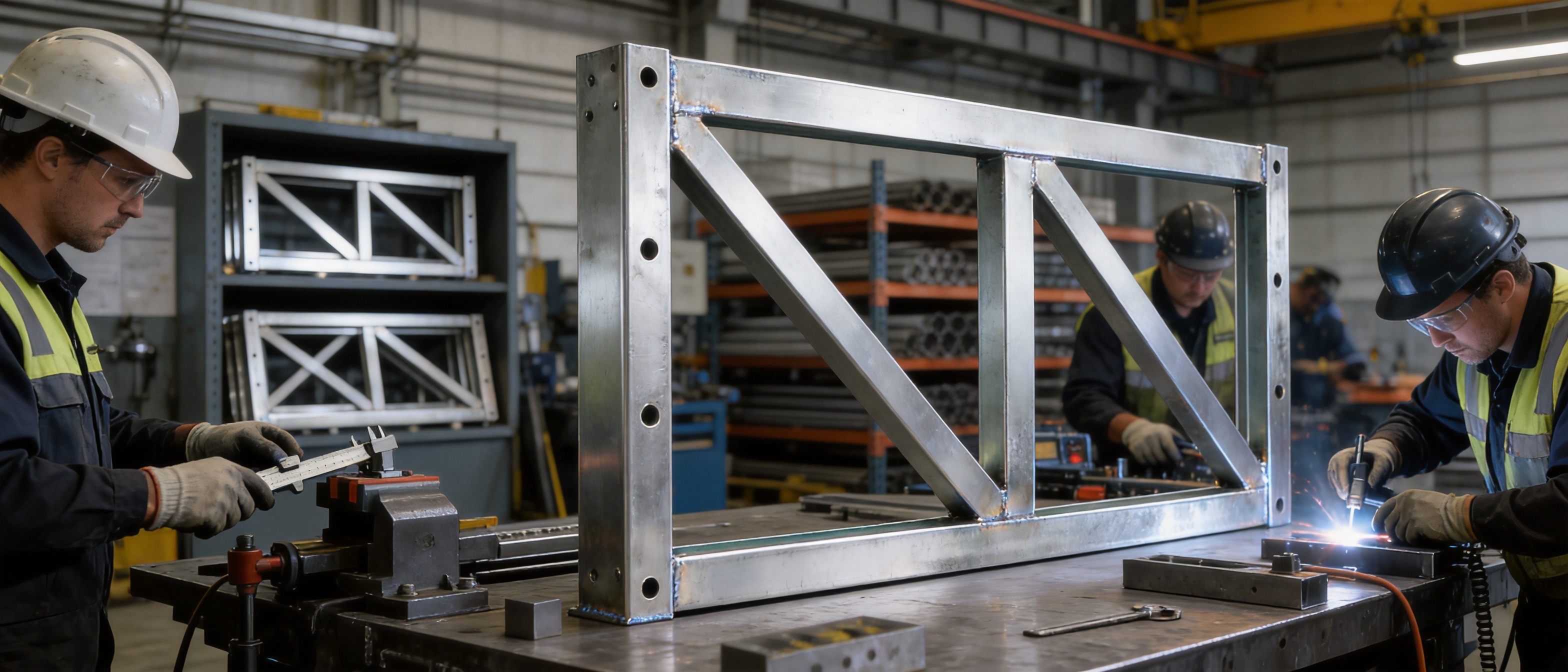
The performance of a vertical support frame begins with the manufacturing process. A structurally suitable design can still lose value if manufacturing tolerances are poorly controlled, welding is inconsistent, or inspection is incomplete. For this reason, the production of HD200 components should follow a disciplined sequence from raw material receipt through final dispatch.
4.1 Engineering Review and Production Planning
The manufacturing process begins with an engineering review of the product drawings, dimensional requirements, material specifications, connection details, and intended system compatibility. The production team confirms the required model, including whether the project requires the 730 or 480 configuration.
Production planning also considers the quantity required, delivery schedule, batch organization, cutting plans, welding sequence, surface treatment, packaging, and transportation. This preliminary control helps prevent component mixing and reduces the possibility of producing a frame with incorrect dimensions or connection details.
4.2 Material Inspection and Traceability
Steel materials should be checked before fabrication. Inspection may include verification of grade, thickness, dimensions, surface condition, and accompanying material documentation. Where required, materials can be marked or recorded to support traceability through the manufacturing process.
Material traceability is valuable for bridge components because it creates a documented connection between the finished product and its raw material source. It also supports quality management, customer inspection, and future maintenance records.
4.3 Precision Cutting and Component Preparation
Steel plates, sections, and connection parts must be cut according to approved dimensions. Precision cutting helps maintain the overall geometry of the frame and reduces the amount of corrective work required during assembly.
Edges and connection surfaces should be prepared appropriately before welding. Burrs, excessive oxidation, oil, moisture, and other contaminants can interfere with welding quality. Proper preparation contributes to more reliable joints and a cleaner finished product.
4.4 Assembly and Fixture Control
During assembly, individual steel members are positioned according to the design geometry. Fixtures, jigs, templates, or other positioning tools can help maintain consistent dimensions between production batches.
Fixture control is especially useful for standardized components that must be interchangeable. A frame that is visually similar to the approved design but dimensionally inaccurate may create installation difficulties or induce unwanted stress when connected to other truss components.
Controlled assembly also helps maintain the required center distances and external dimensions of the Model 730 and Model 480 products. These dimensions must be checked before welding and again after welding because welding heat can introduce distortion.
4.5 Welding Quality Management
Welding is one of the most important stages in the production of a steel support frame. A reliable process should control welding consumables, joint preparation, welding parameters, welder qualifications, preheating requirements where applicable, and inspection procedures.
The welding sequence should be planned to reduce distortion and residual stress. Welded assemblies may require temporary restraints, balanced welding, staged operations, or controlled correction. The objective is to produce strong and consistent joints while preserving the dimensional accuracy of the complete frame.
Visual inspection is normally an essential part of weld quality control. Depending on the project specification and the criticality of the joint, additional non-destructive testing may be applied. Inspection requirements should be established according to applicable standards, design documents, and customer expectations.
4.6 Dimensional Inspection
Dimensional inspection verifies that the finished frame conforms to the required external dimensions, center distances, connection positions, member alignment, and overall geometry.
Inspection may be performed at several stages rather than only at the end of production. In-process checks can identify errors before they are built into the completed frame. Final inspection confirms that the product is ready for coating, packaging, dispatch, or customer acceptance.
For a modular bridge component, dimensional accuracy is not merely a cosmetic issue. It directly affects the ease of installation, the fit of adjacent components, the distribution of forces, and the ability to achieve the intended structural arrangement.
4.7 Surface Treatment, Marking, and Packaging
After fabrication and inspection, the frame may receive the specified surface treatment. Product identification markings can be applied to distinguish the model, batch, or project allocation. Clear marking helps prevent confusion between the 730 and 480 types during storage and erection.
Packaging should protect connection areas and vulnerable surfaces during loading, transport, and unloading. Since bridge components are often moved to remote or difficult project sites, appropriate packaging and handling instructions can reduce the risk of damage before installation.
5. Advantages Compared with Ordinary Fabricated Frames
The HD200 Vertical Support Frame offers several advantages over improvised or non-standard support frames. These advantages are related to compatibility, repeatability, structural integration, production control, and project flexibility.
5.1 Designed as Part of a Complete System
An ordinary fabricated frame may be produced for a single project without a broader connection to a standardized truss system. Although such a frame may appear functional, its performance can be difficult to verify when the connection geometry, load path, and interaction with adjacent components are not standardized.
The HD200 Vertical Support Frame is designed as part of an established HD200 component family. Its function is considered together with horizontal support frames, strengthening chords, truss sections, and other system components. This integrated approach makes it easier for engineers to analyze the complete load path and develop a coordinated erection plan.
5.2 Better Interchangeability
Standardized frames can be used with other compatible HD200 components without the extensive field adjustment often associated with custom-fabricated parts. This is particularly useful for contractors who maintain an inventory of bridge components or who operate across multiple regions.
Interchangeability can lower replacement time and simplify maintenance. If a frame is damaged during transport or service, a compatible spare component can be installed more efficiently than a newly fabricated replacement.
5.3 Controlled Dimensions
Production using defined specifications helps ensure that the frame has repeatable dimensions. This reduces the risk of misalignment, forced connections, site cutting, or unauthorized welding.
Controlled dimensions also support more reliable bridge erection. Crews can work from established assembly procedures and expected connection locations rather than making decisions based on inconsistent field measurements.
5.4 Heavy-Duty Structural Capability
The use of Q355B steel and the HD200 structural concept makes the vertical support frame suitable for demanding applications. It can contribute to bridge systems designed for large spans, heavy traffic, construction loads, and emergency access requirements.
Compared with light-duty temporary supports, the HD200 frame is intended for a more substantial structural role. It can be incorporated into arrangements where stiffness, load transfer, and stability are major design priorities.
5.5 Adaptability for Different Engineering Uses
The frame is not limited to one type of bridge project. It can be used in bridge engineering, large formwork support systems, emergency rescue operations, and other steel support applications where compatible design and adequate structural verification are available.
This adaptability gives contractors and engineering companies more options when planning temporary works. The same general component family may support access bridges, construction platforms, bridge erection operations, or formwork systems, subject to project-specific calculations and approval.
6. Applications in Bridge Engineering
6.1 Temporary and Emergency Bridges
Temporary and emergency bridges are often required when an existing road or bridge has been damaged, when construction access must be established quickly, or when transportation routes need short-term expansion. In these situations, speed is important, but the bridge must still provide dependable structural performance.
The HD200 Vertical Support Frame contributes to rapid modular assembly by providing a standardized component that can be integrated into a preplanned bridge configuration. Its use with HD200 trusses and associated support components can help create a stable route for vehicles, equipment, personnel, or emergency supplies.
Emergency applications may involve difficult ground conditions, limited access, uncertain weather, and restricted construction equipment. A component that is relatively easy to transport, identify, and assemble can provide practical advantages in such environments.
6.2 Semi-Permanent Bridge Structures
Some bridge projects require a service period longer than a short-term emergency installation but do not justify the time or cost of a conventional permanent bridge. Semi-permanent modular bridges can provide an intermediate solution.
In such projects, the vertical support frame helps form part of a durable structural arrangement. The design should consider expected traffic, environmental exposure, maintenance access, corrosion protection, foundation performance, and the planned duration of service.
6.3 Construction Access Bridges
Construction sites frequently require temporary routes for concrete trucks, cranes, excavators, material deliveries, and workers. A modular steel bridge can provide access across rivers, drainage channels, excavations, rail lines, roads, or uneven terrain.
The HD200 Vertical Support Frame can be integrated into a support arrangement designed for construction loads. The responsible engineer must verify the actual vehicle loads, axle configurations, impact factors, span, support conditions, and required safety factors before use.
6.4 Bridge Erection and Launching Operations
Modular bridge components can also be used in bridge erection systems, guide structures, temporary towers, gantry arrangements, and other construction support applications. The vertical support frame may help stabilize temporary structures when it is used within an engineered and approved configuration.
In launching operations, the temporary support system must accommodate changing load positions and construction stages. This makes dimensional accuracy and connection reliability particularly important. The support structure should be checked for each stage rather than evaluated only in the final position.
6.5 Large Formwork Support Systems
The HD200 Vertical Support Frame can also be used in large formwork support systems where a high-capacity steel support arrangement is needed. Large bridge formwork, pier construction, and other concrete works may require temporary structures capable of carrying wet concrete, reinforcement, workers, equipment, and construction impacts.
Formwork support applications require careful attention to vertical alignment, lateral bracing, foundation settlement, load distribution, and construction sequencing. The frame can contribute to such systems, but the complete arrangement must be designed and checked for the specific formwork geometry and construction loads.
7. Installation and Project Planning Considerations
The quality of a bridge component cannot compensate for poor installation. A properly manufactured HD200 Vertical Support Frame must be used according to approved drawings, erection procedures, and engineering calculations.
7.1 Confirming the Correct Model
Before installation, the project team should confirm whether the design requires the Model 730 or Model 480 frame. The model should match the HD200 truss spacing and the approved structural layout.
Product markings, delivery records, drawings, and inspection documents should be checked before components are distributed to the work area. Mixing frame types can cause alignment problems and may prevent proper connection.
7.2 Foundation and Bearing Conditions
The foundation must be capable of supporting the reactions transferred by the bridge or temporary support structure. The bearing surface should be sufficiently level, stable, and prepared for the expected loads.
Where soil bearing capacity is limited, the project may require spread footings, steel grillages, concrete pads, piles, timber mats, or other engineered measures. Settlement can change the geometry of the bridge and increase force concentrations, so foundation behavior must be considered during design and construction.
7.3 Connection and Alignment Control
Connections should be assembled using the specified pins, bolts, fasteners, or other approved connection components. Unapproved drilling, cutting, heating, or welding should not be carried out without engineering authorization.
Alignment should be checked throughout erection. The vertical support frame, truss sections, horizontal support frames, and strengthening chords must be positioned according to the approved configuration. Temporary bracing may be required during intermediate erection stages.
7.4 Inspection Before Loading
Before the bridge is opened to traffic or loaded with construction equipment, the complete structure should be inspected. The inspection should include component identification, connection installation, pin and bolt security, deck support, bracing, bearing conditions, clearances, and visible signs of damage or distortion.
Trial loading, staged loading, or other verification procedures may be required depending on the project, local regulations, and engineering approval. The bridge should not be placed into service until the responsible technical personnel confirm that the installation is complete and suitable for the intended load.
8. Company Manufacturing and Engineering Strengths
Zhenjiang Jinhao Road & Bridge Supporting Engineering Co., Ltd. is based in Zhenjiang, Jiangsu Province, China. Established in 2017, the company has developed from a business focused on construction and industrial materials into an enterprise engaged in the design, manufacturing, erection, and leasing of Bailey bridges, bridge launching gantry systems, hanging baskets, pier formwork, and steel formwork products.
The company’s product range includes Type 321 Bailey truss sections, HD200 or Type 200 Bailey truss sections, Bailey steel bridges, triangular and diamond hanging baskets, bridge steel formwork, and related engineered steel structures. This broader product portfolio provides useful technical context for manufacturing HD200 vertical support components because the company works with several connected categories of bridge and construction equipment.
8.1 Integrated Product Knowledge
A manufacturer that understands truss sections, bridge support systems, launching equipment, formwork, and erection operations can evaluate components from more than a single fabrication perspective. This broader experience helps connect product design with transportation, installation, temporary works, and project planning.
For customers, integrated product knowledge can simplify communication. Instead of treating the vertical support frame as an isolated steel item, the manufacturer can discuss its relationship with trusses, strengthening components, bridge width, erection methods, and support conditions.
8.2 Custom Fabrication and System Planning
Although the HD200 Vertical Support Frame follows standardized dimensions, bridge projects often have different spans, widths, loads, foundations, access conditions, and construction sequences. Jinhao provides customized fabrication, design support, system planning, technical assistance, and quality management for engineering customers.
Customization may involve selecting compatible component quantities, planning bridge arrangements, coordinating support systems, reviewing erection methods, or preparing products for specific project requirements. Customization should preserve the integrity of the standardized HD200 system and remain subject to engineering verification.
8.3 Design, Manufacturing, Erection, and Leasing Capability
The company’s involvement in design, manufacturing, erection, and leasing allows it to serve customers with different procurement models. Some clients may purchase complete bridge systems, while others may require equipment leasing, erection assistance, or technical support for a defined construction period.
This flexibility is valuable for contractors and government organizations that need temporary or semi-permanent access but do not want to maintain a permanent inventory of all bridge components.
8.4 Quality-Oriented Production
For structural products, quality management must cover material selection, fabrication, welding, dimensional control, surface treatment, packaging, and documentation. The company’s focus on engineered steel structures supports a production approach in which the component is manufactured for system use rather than treated as a generic steel fabrication.
Customers should request the relevant product drawings, inspection records, material documentation, coating information, and project-specific quality requirements during procurement. Clear technical communication helps ensure that the supplied component matches the intended engineering application.
9. Transportation, Storage, and Maintenance
Modular bridge components are designed to be transported and reused, but appropriate logistics are still necessary. The HD200 Vertical Support Frame should be loaded in a way that prevents excessive bending, impact, abrasion, or damage to connection features.
During storage, components should be placed on stable supports above standing water and excessive ground moisture. They should be organized by model and batch so that Model 730 and Model 480 frames are not mixed. Identification marks should remain visible and legible.
Before reuse, the frame should be inspected for cracks, significant deformation, damaged welds, severe corrosion, missing identification, or distorted connection areas. Components that have experienced overload, impact, fire, or unauthorized modification should be evaluated by qualified technical personnel before being returned to service.
Maintenance requirements depend on the environment and service duration. Inspection may include checking protective coatings, cleaning accumulated soil or chemicals, repairing damaged paint, confirming connection fit, and recording any visible changes. A documented inspection history can help support decisions about continued use.
10. Selecting the Right Supplier
When purchasing HD200 Vertical Support Frames, buyers should evaluate more than price. The supplier should be able to demonstrate product compatibility, manufacturing capability, material control, dimensional accuracy, and technical support.
10.1 Technical Documentation
Useful documents may include product drawings, dimension tables, material information, welding and inspection records, surface-treatment specifications, installation guidance, packing lists, and certificates required by the project.
Clear documentation reduces the risk of component mismatch and helps the project team plan transportation, storage, assembly, inspection, and maintenance.
10.2 Manufacturing Experience
Experience with Bailey bridges, HD200 trusses, bridge erection systems, formwork, and temporary works can be a significant advantage. A supplier with broader engineering knowledge may be better prepared to identify interface issues before production or delivery.
10.3 Technical Communication
The supplier should be able to discuss the intended span, bridge width, loading, support arrangement, foundation conditions, erection method, service duration, and environmental exposure. Accurate information from the customer allows the manufacturer to recommend a suitable product configuration and identify where project-specific engineering is required.
10.4 Lifecycle Support
For temporary bridges and reusable equipment, service support is important. Customers may need replacement components, inspection assistance, erection guidance, modification planning, or additional equipment for future projects. A supplier capable of supporting the product beyond the initial shipment can provide greater long-term value.
11. Technical Summary
| Characteristic |
HD200 Vertical Support Frame |
| Product category |
Type 200 Bailey truss section component |
| Primary role |
Vertical load support, deformation control, and three-dimensional truss stabilization |
| Available models |
730 type and 480 type |
| Model 730 external dimensions |
1774 × 820 × 50 mm |
| Model 480 external dimensions |
1774 × 570 × 50 mm |
| Center-distance dimension |
1694 × (250 + 230 + 250) mm |
| Material |
Q355B structural steel |
| Compatible systems |
HD200 or Type 200 Bailey truss systems and related engineered support arrangements |
| Typical applications |
Temporary bridges, emergency bridges, semi-permanent bridges, construction access, formwork support, and bridge erection systems |
| Key benefits |
Standardized geometry, heavy-duty material, system compatibility, repeatable fabrication, and flexible engineering use |
12. Frequently Asked Questions
Q1: What is the main purpose of the HD200 Vertical Support Frame?
The main purpose is to support vertical loads, help maintain the geometry of the HD200 truss system, reduce excessive deformation, and contribute to overall structural stability. It works together with horizontal support frames, strengthening chords, truss sections, and foundations.
Q2: What is the difference between the Model 730 and Model 480 frames?
The main difference is the external width and the corresponding HD200 truss spacing arrangement. The Model 730 frame measures 1774 × 820 × 50 mm, while the Model 480 frame measures 1774 × 570 × 50 mm. The correct model should be selected according to the approved bridge configuration.
Q3: What material is used to manufacture the frame?
The frame is manufactured from Q355B structural steel. This material is suitable for load-bearing steel fabrication because it provides a useful combination of strength, weldability, and fabrication performance.
Q4: Can the frame be used for a permanent bridge?
The product is primarily associated with temporary, emergency, semi-permanent, and engineered modular bridge applications. It may be incorporated into a longer-term structure only when the complete system is designed, verified, protected against the environment, inspected, and approved for the intended service period.
Q5: Can it be used in a formwork support system?
Yes, it can be used in large formwork support systems when the arrangement is properly engineered. The support system must be checked for concrete loads, reinforcement loads, workers, equipment, lateral forces, foundation conditions, construction sequence, and allowable deformation.
Q6: Is the vertical support frame a complete bridge by itself?
No. It is one component of an HD200 structural system. A complete bridge generally requires truss sections, deck components, support and connection parts, lateral or horizontal bracing, strengthening components, bearings, foundations, and other elements selected according to the project design.
Q7: Why is dimensional accuracy important?
Dimensional accuracy ensures that the frame fits the compatible HD200 components. It helps maintain the intended center distances, improves erection efficiency, reduces field modification, and supports the correct transfer of forces through the assembled structure.
Q8: Can the frame be reused?
Modular steel bridge components are commonly designed for repeated use, but reuse depends on inspection results and service history. The frame should be checked for damage, deformation, corrosion, cracked welds, and connection problems before each new project.
Q9: What information should a customer provide when requesting a quotation?
Customers should provide the required model, quantity, intended application, bridge span, bridge width, design loading, support arrangement, delivery location, service duration, surface-treatment requirements, and any relevant drawings or technical standards. This information helps the supplier recommend a compatible solution.
Q10: Does the frame eliminate the need for structural calculations?
No. The product is a structural component, not a substitute for project engineering. A qualified engineer must verify the complete bridge or support system, including load effects, stability, connections, foundation capacity, erection stages, and operating conditions.
Conclusion
The HD200 Vertical Support Frame is a purpose-designed component for strengthening and stabilizing HD200 prefabricated steel bridge and heavy-duty truss systems. Its role extends beyond simple vertical support. By working with horizontal support frames, strengthening chords, truss sections, and foundations, it helps create a coordinated three-dimensional force-bearing system.
With Model 730 and Model 480 configurations, the product can match different HD200 truss spacing requirements. Its Q355B structural steel construction supports demanding bridge engineering, construction access, emergency response, semi-permanent bridge, and large formwork support applications.
The main advantages of using a standardized HD200 frame include system compatibility, repeatable dimensions, improved interchangeability, controlled fabrication, heavy-duty structural capability, and flexibility for different engineered uses. These benefits are strengthened when the component is produced by a manufacturer with experience in Bailey bridges, bridge launching systems, hanging baskets, pier formwork, and related steel structures.
Zhenjiang Jinhao Road & Bridge Supporting Engineering Co., Ltd. combines product manufacturing with design support, system planning, erection services, leasing, technical assistance, and quality management. This integrated capability allows customers to obtain more than an individual steel frame. It provides access to a broader bridge and temporary works solution tailored to the requirements of contractors, governments, infrastructure companies, and engineering organizations.
For successful application, the frame must be selected according to the approved HD200 configuration and installed as part of a properly designed system. Correct model selection, foundation preparation, dimensional inspection, connection control, erection sequencing, and maintenance are all essential. When these requirements are addressed, the HD200 Vertical Support Frame can provide a reliable and efficient structural element for demanding modular bridge and construction support projects.
References
1. Product technical information for the HD200 Vertical Support Frame, including Model 730 and Model 480 dimensions and Q355B material specification.
2. General principles of prefabricated modular steel bridge design, erection, inspection, and maintenance.
3. Structural steel fabrication and welding quality-control practices for load-bearing components.
4. Engineering guidance for temporary bridges, emergency access bridges, construction platforms, and semi-permanent modular bridge systems.
5. Technical principles of steel formwork support, temporary works stability, foundation bearing, and construction-stage load management.
6. Manufacturer information concerning Bailey bridges, HD200 and Type 200 truss sections, bridge launching equipment, hanging baskets, pier formwork, and engineered steel structures.


 Français
 Español
 عربى