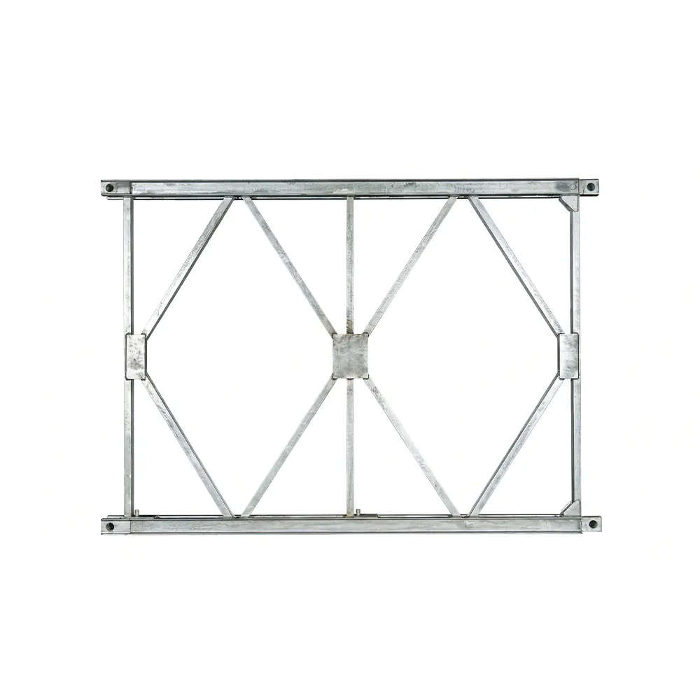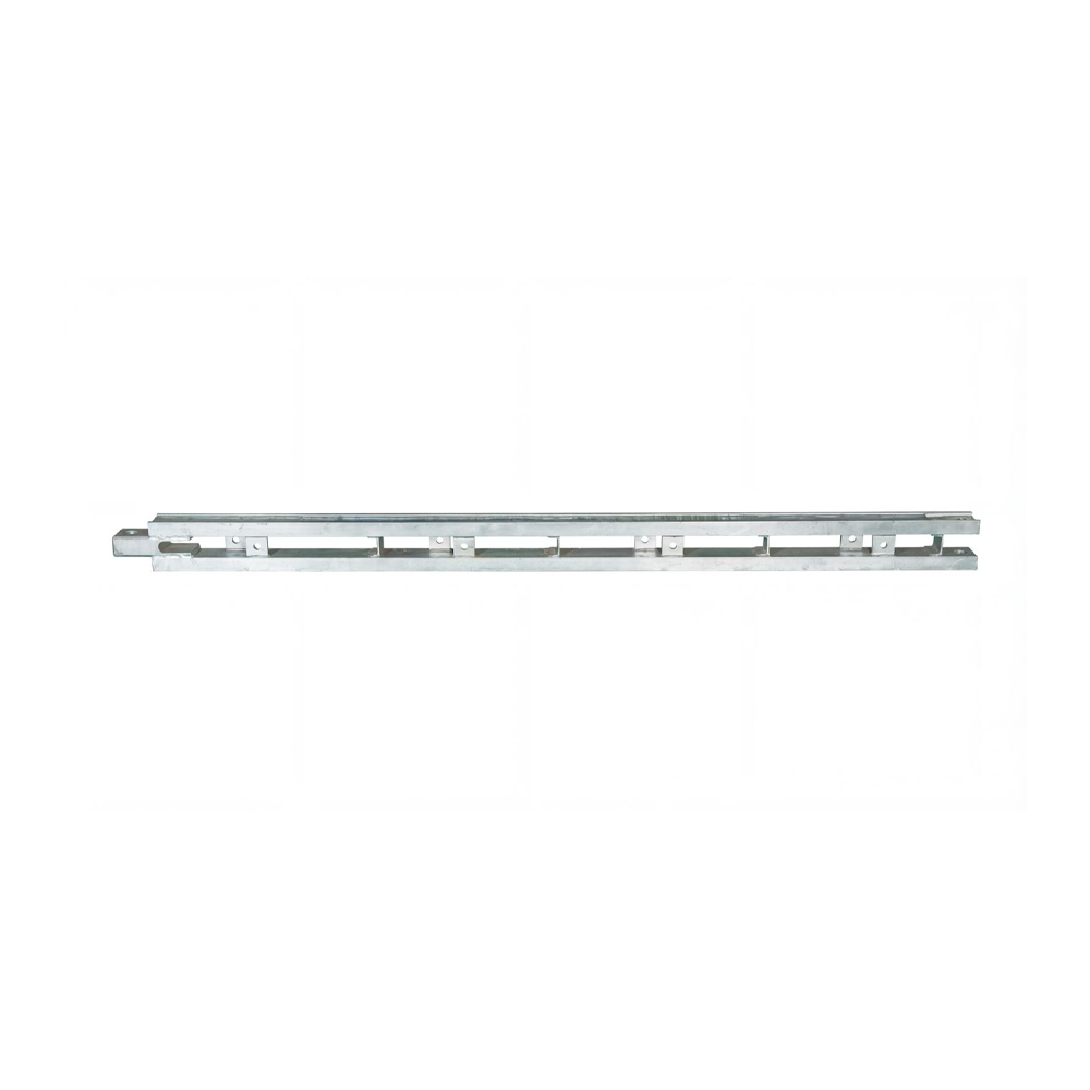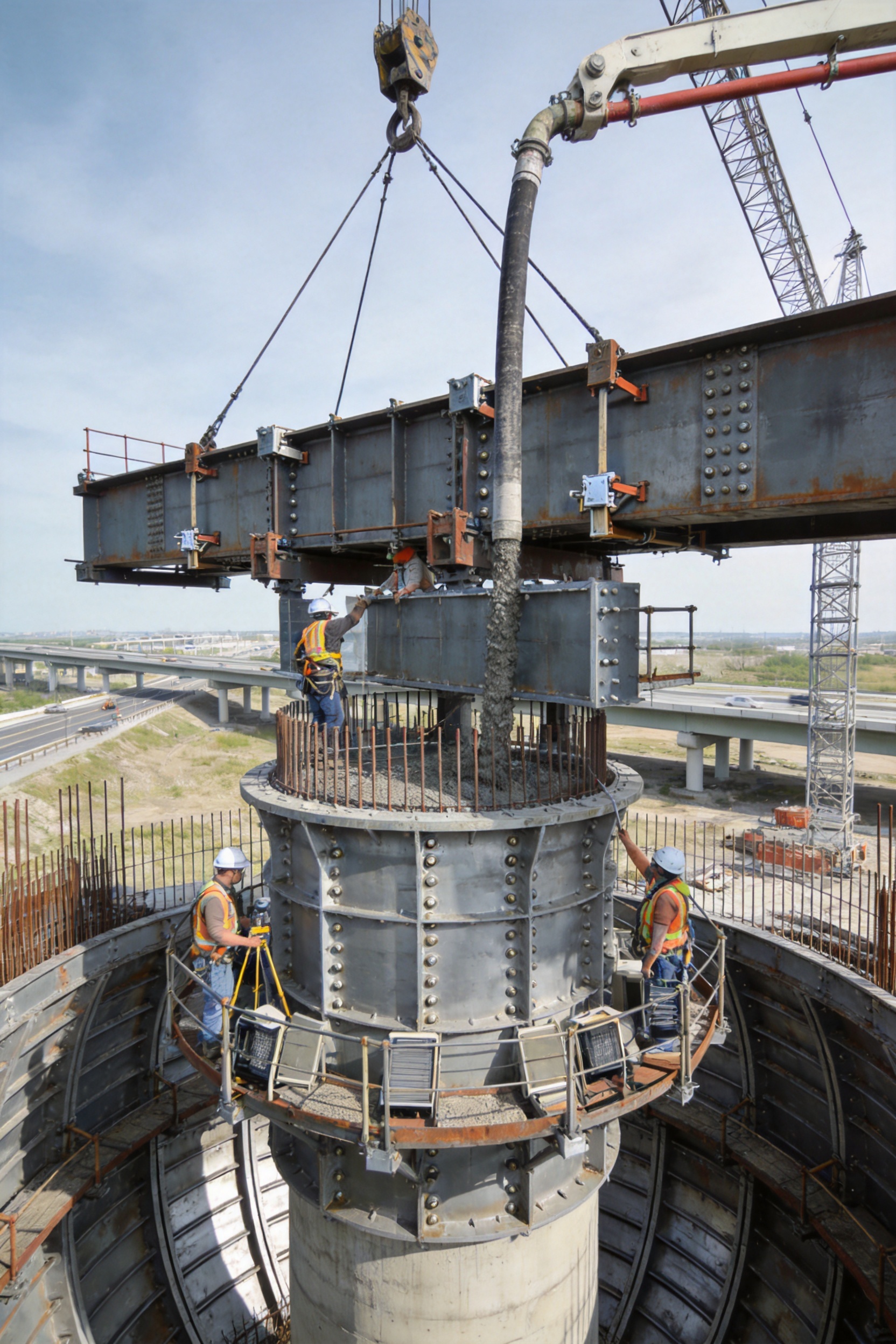
Reliable substructure construction is one of the most important foundations of a safe, durable, and visually consistent bridge. Although pier columns and cap beams are often hidden beneath the deck system, their dimensional accuracy, structural integrity, and surface quality directly influence the alignment, load transfer, durability, and long-term maintenance performance of the entire bridge. For this reason, selecting an appropriate formwork system is not simply a matter of choosing temporary construction equipment. It is an engineering decision that affects productivity, concrete quality, labor requirements, project scheduling, and final construction costs.
Pier and cap beam formwork is a purpose-designed steel formwork solution developed for the controlled casting of bridge substructures. It provides a stable mold for pier columns, pier shafts, and cap beams while maintaining the required geometry during concrete placement, vibration, and curing. Compared with improvised timber formwork or lightly reinforced panel systems, engineered steel formwork offers greater rigidity, better dimensional stability, improved joint sealing, and a longer service life. It is particularly valuable on highway and railway bridge projects where repeated construction, strict tolerances, high-strength concrete, and consistent appearance are required.
The system supplied by Zhenjiang Jinhao Road & Bridge Supporting Engineering Co., Ltd. is designed around these practical construction requirements. The company combines structural design, steel fabrication, formwork assembly, technical support, and project-oriented customization to provide solutions for circular, square, rectangular, and irregular pier and cap beam configurations. Its formwork products are part of a broader portfolio that includes Bailey bridges, bridge launching gantries, hanging baskets, and other engineered steel structures. This background in bridge construction equipment enables the company to understand the relationship between substructure formwork, temporary works, erection planning, and the overall bridge-building process.
The central value of the product lies in its ability to create a repeatable, controlled, and efficient concrete-forming process. A well-designed system reduces the possibility of deformation, leakage, misalignment, honeycombing, and surface defects. It also allows construction teams to reuse the same formwork across multiple piers, helping standardize the work and lower the cost per completed structural element.
What Is Pier and Cap Beam Formwork?
Pier and cap beam formwork is a modular steel mold assembly used to shape and support concrete during the construction of bridge piers and their upper cap beams. The system generally consists of steel panels, stiffening ribs, connection plates, positioning clips, adjustable supports, access components, and sealing interfaces. Depending on the project requirements, it may be designed as a split circular mold, a multi-panel rectangular mold, a combined pier-and-cap configuration, or a customized system for non-standard geometries.
The pier formwork creates the vertical shaft or column that transfers loads from the bridge superstructure into the foundation. The cap beam formwork forms the horizontal or transverse member positioned at the top of the pier. This beam supports bearings, girders, deck segments, or other superstructure components. Because the cap beam often includes bearing seats, reinforcement congestion, embedded items, and complex transitions, its formwork must provide accurate control over dimensions and openings.
During installation, reinforcement cages and embedded components are positioned inside the formwork. The panels are then assembled around the reinforcement and secured using approved connections and supports. The system must remain stable when subjected to the pressure of fresh concrete, the impact of concrete placement, and the vibration used to eliminate voids. Once the concrete has reached the required demolding strength, the panels can be released, removed, cleaned, inspected, and prepared for the next use.
Unlike basic site-made molds, engineered steel formwork is developed to perform consistently over many construction cycles. The design considers panel dimensions, load paths, stiffener spacing, connection positions, lifting arrangements, access requirements, and the expected rate of concrete placement. This makes the system a construction tool as well as a temporary structural assembly.
Core Advantages of the Formwork System
Sufficient Rigidity Under Concrete Pressure
Fresh concrete produces significant lateral pressure on vertical form faces. The pressure can increase when concrete has high slump, when placement is rapid, or when vibration is intensive. If panels or supports are insufficiently rigid, the formwork may bulge, twist, or open at the joints. Such movement can create dimensional errors, uneven surfaces, misaligned edges, and difficult repair work.
The pier and cap beam formwork is designed with reinforced steel panels and strategically arranged stiffening members. These components distribute pressure across the formwork frame and transfer forces into the supporting system. A rigid assembly helps preserve the designed cross-section during pouring and reduces the risk of local deformation. This is particularly important for tall piers, large cap beams, high-strength concrete, and structures with demanding geometric tolerances.
Rigidity also improves the repeatability of construction. When a steel mold maintains its shape from one cycle to the next, the dimensions of successive piers remain more consistent. Contractors can therefore reduce the need for repeated adjustments, corrective measurements, and post-pouring repairs.
Excellent Joint Sealing
Formwork joints are common locations for leakage. If cement paste escapes through gaps between panels, the finished concrete may show fins, honeycombing, exposed aggregate, or irregular edges. Leakage can also make panel removal more difficult and increase cleaning time.
The system uses carefully matched panel interfaces and sealing arrangements to limit the escape of cement slurry. Properly tightened connections maintain contact between adjoining panels, while suitable sealing materials or joint treatments can be applied according to the concrete mix and project conditions. Good joint sealing contributes to a cleaner concrete surface and reduces the amount of grinding, patching, and surface treatment required after demolding.
Joint sealing is especially valuable when the bridge has exposed piers or when the owner requires a high level of visual quality. A smooth and uniform surface improves the appearance of the completed structure and can reduce the long-term maintenance associated with defective surface zones.
Dedicated Positioning Clips for Accurate Alignment
Positioning clips and related alignment components help control the relative location of panels during assembly. They reduce unwanted movement and assist workers in achieving the specified pier diameter, width, thickness, and verticality. For cap beams, positioning devices help maintain the required length, depth, bearing-seat arrangement, and relationship to the pier centerline.
Accurate positioning is important because small errors at the pier level can create larger coordination problems above. A pier that is out of plumb may affect the position of the cap beam, bearing assemblies, girder lines, deck joints, and expansion devices. By providing a defined and repeatable positioning method, the formwork system supports better geometric control throughout the bridge construction sequence.
Smooth Concrete Surfaces Without Extensive Finishing
High-quality steel form faces create a smooth contact surface for concrete. When the panels are clean, properly assembled, and treated with a suitable release agent, the resulting concrete can achieve a consistent finish with clear edges and minimal surface blemishes. The product is intended to allow the concrete surface to remain smooth and flawless after demolding when proper construction procedures are followed.
Reducing finishing work has both economic and technical benefits. It lowers labor consumption, shortens the time between demolding and the next construction activity, and reduces the possibility of inconsistent repair colors or textures. It also helps contractors meet appearance requirements without relying on extensive surface grinding, mortar patching, or cosmetic coating.
Adaptability to Different Cross-Sections
Bridge piers do not all have the same shape. Depending on structural calculations, environmental conditions, architectural requirements, and construction methods, a project may include circular columns, square piers, rectangular shafts, wall-type piers, tapered members, or irregular forms. Cap beams may also vary in width, depth, overhang, bearing-seat arrangement, and connection geometry.
A modular formwork approach allows the system to be adapted to multiple cross-sections. Circular formwork can be configured with curved panels, while square and rectangular piers can use flat steel panels connected at corners. Customized panels and transition pieces can be developed for irregular shapes or special details. This flexibility allows contractors to use a coordinated formwork strategy across different bridge sections instead of relying on completely separate temporary systems for every pier type.
Suitability for Standardized Mass Construction
Large highway and railway projects often include dozens or hundreds of similar piers. In such cases, the productivity of each construction cycle has a major influence on the total project schedule. A reusable steel formwork system supports a standardized sequence of reinforcement placement, panel assembly, inspection, concrete pouring, curing, demolding, cleaning, and relocation.
Once workers become familiar with the system, setup time can be reduced and quality checks can be performed using repeatable procedures. The same panel set can be moved from one pier to another by crane or other suitable lifting equipment. This creates an efficient production rhythm and makes it easier for project managers to plan labor, concrete deliveries, lifting operations, and inspection activities.
Compatibility with High-Strength Concrete
High-strength and high-performance concrete may generate demanding pressure and require careful placement and vibration. Its low water-binder ratio, mineral additives, high flowability, or rapid strength development can influence formwork loading and demolding procedures. A stable steel system is well suited to these conditions because it provides stronger resistance to deformation than many temporary alternatives.
The formwork does not replace proper concrete engineering. Concrete mix design, placement speed, temperature control, vibration technique, curing, and strength testing remain essential. However, the formwork provides a reliable physical boundary that allows these processes to be controlled more effectively.
Advantages Over Conventional and Lower-Grade Alternatives
Comparison with Timber Formwork
Timber formwork can be useful for small or irregular works, but its performance often depends heavily on the quality of the materials and the skill of site fabrication. Timber can absorb moisture, swell, warp, split, or lose dimensional accuracy after repeated use. Joint sealing may also be inconsistent, especially when panels are assembled under changing site conditions.
Steel formwork offers better dimensional stability and a longer reuse cycle when maintained correctly. Its panel faces are more uniform, its stiffening system can be engineered for the expected loads, and its connections can be designed for repeatable assembly. These characteristics are particularly advantageous for mass bridge construction, where a temporary saving in initial fabrication may be outweighed by repeated repair, replacement, labor, and finishing costs.
Comparison with Improvised Site-Fabricated Panels
Improvised panels may lack a coordinated load path. Their supports, connectors, and stiffeners are sometimes added after problems appear during trial assembly. This can increase safety risks and make it difficult to verify alignment before concrete placement. Site-fabricated systems may also vary from one pier to the next, reducing standardization.
A purpose-designed formwork system is developed as an integrated assembly. Panel geometry, connection points, reinforcement clearances, lifting arrangements, and support locations are considered together. This engineering approach improves predictability and makes the system easier to inspect, operate, and reuse.
Comparison with Thin or Poorly Reinforced Steel Formwork
Not all steel formwork provides the same performance. Thin panels with inadequate stiffening may deform under pressure, while poorly manufactured connection holes can make assembly difficult. Weak corner details and inaccurate panel dimensions can lead to leakage and misalignment.
The product’s competitive value comes from combining steel construction with sufficient rigidity, precise fabrication, carefully arranged joints, and dedicated positioning components. The result is not merely a metal skin but a coordinated formwork system intended for bridge construction conditions.
Lower Lifecycle Cost
The most meaningful cost comparison should include the entire construction cycle rather than only the purchase price. Important cost factors include fabrication, transportation, assembly, labor, concrete repair, finishing, demolding time, cleaning, maintenance, reuse, and eventual storage or rental value.
Durable steel formwork can reduce the cost per pier by spreading the initial investment over many uses. Its smooth surfaces can reduce finishing labor, while its repeatable geometry can minimize corrective work. For contractors working on multiple projects, the equipment may also serve as a reusable asset that supports future bridge construction.
| Evaluation Factor | Conventional Timber or Improvised Formwork | Engineered Pier and Cap Beam Steel Formwork |
|---|
| Dimensional stability | Can change with moisture, wear, and repeated assembly | High stability when correctly fabricated and maintained |
| Joint performance | Depends strongly on site workmanship | Designed panel interfaces and dedicated connections |
| Resistance to concrete pressure | May require extensive temporary bracing | Integrated stiffening and support arrangement |
| Surface finish | May require patching or additional finishing | Smooth steel contact face supports consistent appearance |
| Reuse potential | Limited or variable | Suitable for repeated construction cycles |
| Shape adaptability | Flexible but labor-intensive to modify | Modular and customizable for defined cross-sections |
| Mass construction efficiency | Setup methods may vary between locations | Supports standardized installation and relocation |
| Quality control | Often dependent on individual site fabrication | Factory fabrication and inspection improve consistency |
Manufacturing and Engineering Strengths
Project-Based Design Development
The manufacturing process begins with understanding the bridge design and construction sequence. Important input data may include pier dimensions, cap beam geometry, concrete pressure assumptions, reinforcement layout, embedded components, access requirements, lifting limitations, and the planned number of reuse cycles.
Designers review these requirements to determine panel sizes, joint locations, stiffener arrangements, support points, and connection systems. For a circular pier, the design must maintain the required radius and ensure that the curved panels close accurately. For a square or rectangular pier, corner connections must preserve the angle and prevent opening during pouring. For cap beams, the design must accommodate overhangs, bearing seats, recesses, chamfers, and interfaces with the pier shaft.
Project-based design is especially important for irregular structures. Standard panels may be combined with customized inserts, transition sections, or special brackets to produce a form that matches the approved structural drawings. This approach provides the flexibility of customized equipment while retaining the efficiency of modular steel fabrication.
Material Preparation and Traceability
Steel formwork performance depends on the quality and consistency of its raw materials. Plate, section steel, stiffeners, connection components, lifting points, and accessories must be selected according to the required strength, stiffness, weldability, and service conditions.
Material preparation typically includes receiving inspection, dimensional verification, surface condition checks, marking, cutting, and sorting. Clear identification of components helps ensure that the correct materials are used in the correct assemblies. It also supports production organization and makes future maintenance or replacement more efficient.
For bridge formwork, material traceability is valuable because the equipment may be reused across several projects. Records relating to component identification, fabrication, repair, and inspection can help operators understand the history of the system and plan preventive maintenance.
Precision Cutting and Forming
Accurate cutting is necessary to maintain panel dimensions, joint alignment, and the correct relationship between steel plates and stiffening members. Modern fabrication methods can improve repeatability and reduce dimensional variation, particularly when several panels share the same geometry.
Curved panels require additional control because even small deviations in radius can create gaps or uneven joints when the mold is closed. Flat panels also require accurate edge preparation so that adjacent surfaces meet properly. Components are prepared according to production drawings, with attention to hole positions, corner angles, weld allowances, and assembly references.
Controlled Welding and Structural Assembly
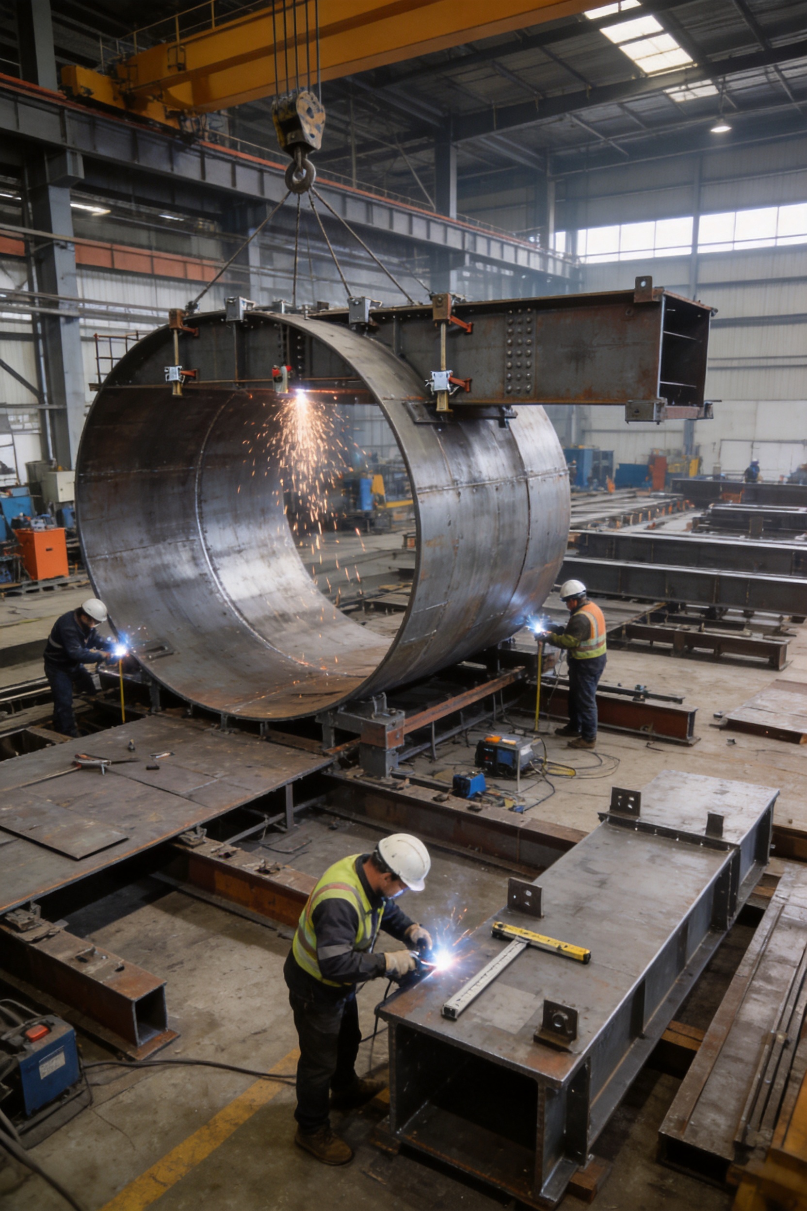
Welding connects the face plates, ribs, frames, brackets, lifting components, and other structural parts of the formwork. Welding quality affects the stiffness, durability, and service life of the panels. A controlled manufacturing process therefore requires appropriate joint preparation, welding sequence, distortion control, and visual inspection.
Welding sequences are planned to limit heat distortion. If a panel becomes distorted during fabrication, its contact face may not meet the required flatness or curvature. The manufacturing team can use fixtures, temporary supports, and staged welding to maintain alignment. After welding, important dimensions are checked against the design drawings.
Assembly verification is another important stage. Panels may be trial-fitted in the factory or arranged using reference fixtures to confirm that connection holes, clips, corners, and interfaces align correctly. This helps identify manufacturing issues before the equipment reaches the construction site.
Surface Treatment and Form-Face Preparation
The concrete-facing surface must be smooth, clean, and suitable for the intended release system. Surface preparation can include cleaning, grinding of unacceptable irregularities, correction of weld spatter, edge treatment, and protective coating where required by the project environment.
The quality of the form face directly influences the appearance of the concrete. Uneven projections, contamination, damaged edges, or excessive rust can transfer defects to the finished pier. Proper surface treatment therefore supports both visual quality and ease of demolding.
Dimensional and Functional Inspection
Inspection should cover more than the appearance of the steel. Important checks include panel length, width, height, radius, diagonal measurements, corner angles, hole positions, connection fit, lifting-point condition, stiffener alignment, and the flatness or curvature of the concrete-facing surface.
Where appropriate, the complete or partial assembly can be checked before shipment. This provides an opportunity to verify that the formwork closes correctly, that positioning clips operate as intended, and that the planned installation sequence is practical. The aim is to deliver equipment that can be installed efficiently rather than requiring extensive correction at the project site.
Packaging, Identification, and Delivery Planning
Steel formwork components must be protected during transportation and handling. Components can be marked according to their assembly position, pier type, or project reference. Organized identification reduces the risk of confusion when several panel sizes are delivered together.
Delivery planning also considers lifting weight, loading sequence, storage space, and access to the construction area. Properly arranged shipments can reduce unloading time and help the contractor move directly from delivery to assembly.
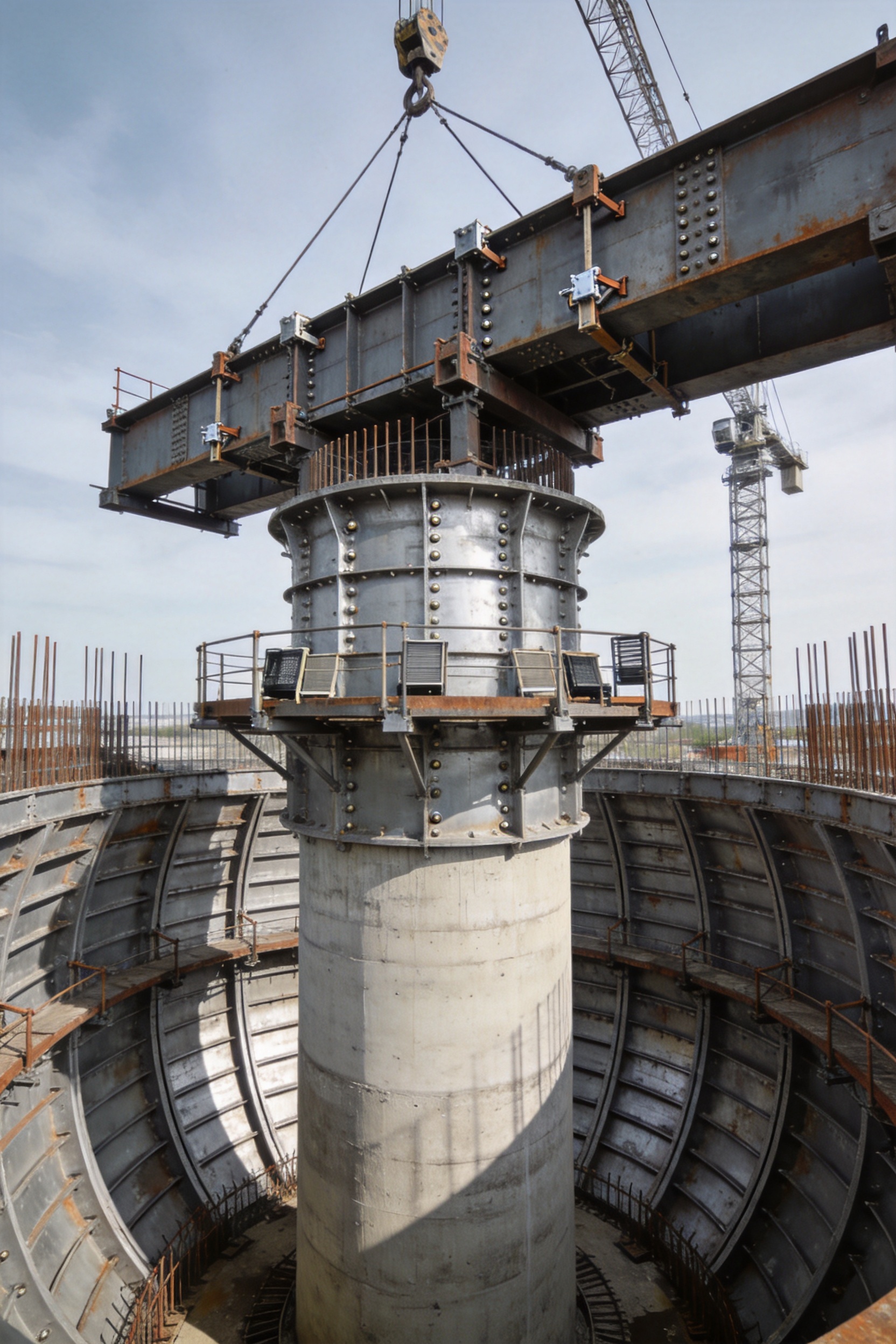
Application in Different Bridge Construction Conditions
Highway Bridges
Highway bridges frequently involve repeated piers with standardized dimensions. The formwork system is well suited to this environment because the same or similar panels can be reused across multiple locations. A standardized work cycle can include foundation preparation, reinforcement installation, formwork erection, verticality inspection, concrete placement, curing, demolding, and relocation.
For wide highway structures, cap beam formwork may need to accommodate multiple bearing positions and substantial overhangs. The system can be designed around the approved cap beam drawing so that openings, recesses, chamfers, and bearing-seat details are formed accurately.
Railway Bridges
Railway bridge construction often requires strict control of alignment and geometry because the superstructure may have limited tolerance for deviations. Pier verticality, cap beam elevation, and bearing-seat position are critical to the correct installation of girders or other railway bridge components.
Steel formwork supports a controlled construction process and can be integrated into a broader quality management plan. Repeated use is particularly beneficial on viaduct projects with many similar spans, where productivity and dimensional consistency are closely connected.
Urban and Municipal Bridges
Urban bridge sites may have limited space, restricted working hours, nearby buildings, traffic constraints, and complex access conditions. A modular formwork system can be planned for staged delivery and efficient lifting. Its reusable nature can reduce the amount of temporary material stored on a congested site.
Appearance may also be especially important for urban infrastructure. Smooth, consistent pier surfaces reduce the need for visible repair and contribute to a more finished appearance in areas where the bridge is viewed closely by the public.
Special and Irregular Pier Shapes
Some bridge designs use tapered piers, sculpted columns, flared shafts, or other non-standard shapes. These structures require careful coordination between the formwork, reinforcement cage, embedded components, and concrete placement method.
Customized steel panels can be developed for these conditions. The main advantage is that the system can preserve the geometry of the approved design while retaining the stability and repeatability associated with steel construction. Before fabrication, the manufacturer and contractor should confirm the dimensions, construction joints, demolding direction, lifting strategy, and access arrangements.
Installation and Construction Workflow
Site Preparation
Before formwork installation, the construction area should be checked for foundation condition, access, crane reach, working platforms, reinforcement readiness, and safe lifting space. The pier centerline and reference elevations should be clearly established. Any construction debris, standing water, or obstructions around the base must be removed.
Panel Inspection
Panels should be inspected after delivery and before assembly. Workers should check for transportation damage, contamination, deformation, missing connectors, damaged threads, and condition of lifting points. The concrete-facing surface should be cleaned, and any defects that could affect the finished concrete should be corrected.
Assembly Around Reinforcement
The panel sequence depends on the pier type and project design. Panels are generally positioned around the reinforcement cage while maintaining the specified concrete cover. Connections are installed progressively, and the formwork is supported so that it remains stable before all components are fully tightened.
For cap beams, reinforcement congestion may require a carefully planned sequence. The contractor should confirm that reinforcing bars, ducts, anchor assemblies, bearing-seat inserts, drainage elements, and other embedded components do not interfere with panel installation or removal.
Alignment and Verticality Control
After assembly, the pier formwork is checked for centerline position, verticality, cross-section, elevation, and joint closure. Positioning clips assist this process, but survey instruments and approved site measurement procedures remain necessary. Adjustments should be completed before concrete placement.
The cap beam is checked in relation to the pier axis and the bridge alignment. Bearing seats and other critical details require special attention because dimensional errors may affect the superstructure installation.
Release Agent Application
A suitable release agent should be applied evenly to the clean form face. Excessive application can cause surface discoloration or affect concrete quality, while insufficient application may make demolding difficult. The selected product should be compatible with the concrete mix, formwork material, environmental conditions, and project appearance requirements.
Concrete Placement
Concrete should be placed according to an approved sequence and at a controlled rate. Sudden, uneven loading can increase local pressure and cause unnecessary stress on the formwork. Concrete should be distributed to avoid unbalanced forces, and vibration should be performed carefully to remove air without damaging reinforcement or embedded items.
Workers should monitor the formwork during pouring. Any abnormal movement, leakage, noise, or connection displacement should be investigated immediately. Concrete placement should not continue if the system shows signs of instability or if the actual conditions differ significantly from the approved method statement.
Curing and Demolding
Concrete must achieve the specified strength before the formwork is removed. The required time depends on the concrete mix, temperature, curing conditions, structural design, and project specifications. Premature demolding can damage edges, reduce surface quality, or compromise structural performance.
Once demolding is approved, connections are released in a controlled sequence. Panels should not be forced away from the concrete with uncontrolled impact. Suitable lifting equipment and designated lifting points should be used. After removal, the panels are cleaned, inspected, lightly maintained, and prepared for the next cycle.
Quality Management and Long-Term Performance
Construction Quality Control
Formwork quality is closely connected to concrete quality. A strong steel system provides the necessary physical support, but good results also require accurate survey work, correct reinforcement placement, appropriate release-agent application, controlled concrete delivery, adequate vibration, and proper curing.
A practical inspection plan should include checks before assembly, during assembly, before pouring, during pouring, and after demolding. These checks may cover dimensions, verticality, panel cleanliness, joint tightness, reinforcement cover, embedded components, support condition, concrete pressure, and surface finish.
Maintenance Between Uses
Reusable formwork performs best when it is maintained between construction cycles. Concrete residue should be removed promptly without damaging the form face. Connectors should be cleaned and checked for wear. Bent or damaged components should be repaired or replaced before the next installation.
Panels should be stored on stable supports in a way that prevents unnecessary deformation. Concrete-facing surfaces should be protected from impact, and small areas of coating damage or corrosion should be treated before they become more serious. A simple maintenance record can document the number of uses, repairs, inspections, and storage conditions.
Safety Considerations
Steel panels can be heavy, and lifting operations must be planned by qualified personnel. Workers should remain clear of suspended loads and use appropriate personal protective equipment. Platforms, ladders, handrails, and access routes must be installed and used according to the project safety plan.
Formwork stability should be confirmed before workers enter the area or concrete placement begins. Connections, braces, supports, and lifting accessories must be suitable for the actual loads. Any modification to the system should be reviewed by responsible technical personnel rather than performed without approval.
Why Manufacturer Capability Matters
The performance of pier and cap beam formwork depends not only on the design concept but also on the ability of the manufacturer to turn that concept into accurate, durable, and usable equipment. A manufacturer with experience in bridge steel structures is better positioned to understand the practical relationship between formwork geometry, reinforcement congestion, crane operations, construction sequencing, and superstructure alignment.
Zhenjiang Jinhao Road & Bridge Supporting Engineering Co., Ltd. was established in 2017 and operates from an industrial location in Jiangsu Province, China. The company has developed from a business focused on construction and industrial materials into a comprehensive enterprise involved in the design, manufacture, erection, and leasing of bridge-related steel equipment.
Its product range includes Bailey steel bridges, Type 321 Bailey truss sections, HD200 and Type 200 Bailey truss sections, triangular and diamond hanging baskets, bridge launching gantry systems, pier formwork, and other steel formwork products. This broad portfolio provides practical knowledge of temporary bridge systems, bridge erection, segmental construction, and structural steel fabrication.
The company serves contractors, government-related engineering organizations, and construction companies seeking customized steel bridge solutions. Its service capabilities include design and system planning, customized fabrication, technical support, erection assistance, leasing, and quality management. These capabilities are useful when a project requires more than a standard catalog item.
Integrated Design and Fabrication
Integrated service reduces the risk of disconnects between design drawings and manufactured components. When the same technical team coordinates geometry, panel fabrication, connection details, and site requirements, it becomes easier to address special conditions such as unusual pier shapes, restricted crane access, or a high number of reuse cycles.
Experience with Temporary and Permanent Construction Systems
Bailey bridges, launching gantries, hanging baskets, and steel formwork all require attention to structural behavior, assembly sequence, lifting, connection reliability, and site safety. Experience across these product categories helps the company approach formwork as part of a complete bridge construction system.
Customization for Project Requirements
Every bridge project has its own combination of dimensions, construction methods, schedule requirements, and site limitations. Customization may involve panel dimensions, pier shape, cap beam layout, access provisions, lifting points, support arrangements, or the number of formwork sets required. A project-specific solution can be more effective than forcing a standard product into an unsuitable application.
Support for Domestic and International Projects
Bridge contractors working across different regions may require clear technical communication, organized component identification, shipping coordination, and practical installation guidance. A manufacturer experienced in supplying engineered steel products can support these needs through project documentation, fabrication coordination, and technical service.
Economic and Environmental Benefits
Reusable steel formwork can improve project economics by reducing repeated material consumption. Instead of fabricating new timber molds for every pier, contractors can use a durable panel system through multiple cycles. This may reduce waste, labor, and disposal requirements, particularly on large projects.
Steel is also suitable for repair, refurbishment, and recycling at the end of its useful service life. A maintained formwork system can remain in circulation for future projects, extending the value of the original investment. The environmental benefit depends on manufacturing energy, transportation, maintenance, and actual reuse, but repeated deployment generally improves the resource efficiency of the equipment.
Better concrete surface quality can provide an additional sustainability advantage. Reduced patching and finishing mean less repair mortar, fewer supplementary materials, and less labor-intensive rework. More consistent construction can also reduce the risk of demolition and recasting caused by major dimensional or surface defects.
Selection Guidelines for Contractors and Project Owners
Before selecting a pier and cap beam formwork system, the project team should define the required pier types, dimensions, concrete pressures, construction cycle, lifting equipment, and expected reuse quantity. The contractor should also determine whether the formwork will be purchased, leased, or used as part of a broader bridge construction package.
Important technical questions include:
What are the exact cross-sections and height ranges of the pier columns?
Does the project include circular, square, rectangular, tapered, or irregular shapes?
What are the cap beam length, width, depth, overhang, and bearing-seat requirements?
How will reinforcement cages and embedded components be installed inside the formwork?
What concrete strength, slump, placement rate, and vibration method will be used?
What tolerances apply to verticality, flatness, alignment, and bearing-seat position?
How many reuse cycles are expected, and how quickly must the formwork be relocated?
What crane capacity, lifting points, working platforms, and storage areas are available?
Will the project require technical support, erection assistance, or a complete system plan?
Answers to these questions allow the manufacturer to prepare a more accurate design and commercial proposal. They also help prevent late changes that could affect fabrication, delivery, or construction scheduling.
Recommended Best Practices
Use approved drawings and method statements for every formwork configuration. Do not assume that a panel arrangement suitable for one pier type is automatically suitable for another.
Inspect all components before each use. Pay special attention to connection holes, clips, bolts, braces, lifting points, welds, and concrete-facing surfaces.
Keep the panels clean and apply release agent consistently. Surface contamination is one of the simplest causes of poor concrete appearance.
Confirm reinforcement cover and embedded-item locations before closing the formwork. Small obstructions can prevent proper panel seating and create unwanted pressure points.
Check verticality and alignment using suitable survey equipment. Positioning clips improve control but do not replace measurement and inspection.
Control concrete placement speed and sequence. Avoid sudden, unbalanced loading and monitor the formwork throughout the pour.
Allow sufficient concrete strength before demolding. Follow the approved project requirements rather than relying only on elapsed time.
Clean, inspect, and store the panels correctly after removal. Proper maintenance is essential to achieving the full reuse potential of steel formwork.
Frequently Asked Questions
What types of bridge elements can this formwork produce?
The system is intended for pier columns and cap beams used in highway, railway, municipal, and related bridge projects. It can be adapted for circular, square, rectangular, and irregular cross-sections, subject to project-specific design.
Can the formwork be customized for a non-standard pier?
Yes. Customized steel panels, inserts, transition sections, connection details, and support arrangements can be developed according to approved structural drawings and construction requirements.
What is the main advantage over timber formwork?
The main advantages are greater rigidity, better dimensional stability, improved joint sealing, smoother concrete surfaces, and stronger potential for repeated use. These features can reduce rework and improve construction consistency.
Does the formwork eliminate all concrete finishing work?
When the panels are accurately fabricated, properly assembled, clean, and correctly treated with release agent, the concrete surface can be smooth and consistent with little or no additional finishing. Actual results also depend on concrete quality, vibration, curing, and site workmanship.
Is it suitable for high-strength concrete?
Yes, the rigid steel structure is suitable for projects using high-strength or high-performance concrete, provided that the formwork design is checked against the expected concrete pressure and the placement method is properly controlled.
How does the system control pier verticality?
Dedicated positioning clips, accurately fabricated panels, braces, and adjustment supports work together to control alignment. Survey checks are still required before and during concrete placement.
Can the same formwork be reused for multiple piers?
Yes. Reuse is one of the main benefits of modular steel formwork. The number of reuse cycles depends on panel quality, handling practices, cleaning, maintenance, project conditions, and the specific design.
What should be checked before pouring concrete?
The project team should check panel dimensions, joint tightness, verticality, centerline, support stability, reinforcement cover, embedded items, release agent, access platforms, lifting or bracing arrangements, and the approved concrete placement sequence.
How is the formwork removed?
After the concrete reaches the required demolding strength, connections are released in a controlled sequence and panels are lifted or moved using suitable equipment. The exact sequence should follow the project method statement and avoid impact or uncontrolled prying.
Can the manufacturer provide more than the steel panels?
Depending on the project, services may include design and system planning, customized fabrication, technical support, erection assistance, leasing, and quality management. The required scope should be confirmed during project planning.
What information is needed for a quotation?
Useful information includes pier and cap beam drawings, quantities, dimensions, cross-sections, concrete data, construction schedule, reuse requirements, lifting limitations, delivery location, and any special surface-finish or tolerance requirements.
Conclusion
Pier and cap beam formwork is a critical component of efficient and high-quality bridge substructure construction. Its value extends beyond creating a temporary mold. A properly engineered system controls geometry, resists concrete pressure, seals joints, improves surface quality, supports repeated use, and contributes to a predictable construction cycle.
The system described in this article is distinguished by sufficient rigidity, excellent joint sealing, dedicated positioning clips, smooth concrete-facing surfaces, and adaptability to a wide range of pier and cap beam shapes. These advantages make it suitable for standardized mass construction, high-strength concrete work, highway bridges, railway viaducts, municipal infrastructure, and projects with demanding appearance requirements.
Its competitiveness is strengthened by the manufacturer’s broader experience in bridge steel structures and temporary works. Through design, fabrication, erection, leasing, technical support, and customized engineering, Zhenjiang Jinhao Road & Bridge Supporting Engineering Co., Ltd. can support contractors that need coordinated and reliable bridge construction equipment.
For project owners and contractors, the best formwork choice is the one that combines technical performance with practical installation, repeatable quality, manageable lifecycle cost, and dependable manufacturer support. When these factors are considered together, modular steel pier and cap beam formwork becomes a valuable investment in bridge safety, productivity, appearance, and long-term construction efficiency.
References
American Concrete Institute. Guide to Formwork for Concrete Structures.
American Association of State Highway and Transportation Officials. Bridge Construction Specifications.
European Committee for Standardization. Temporary Works and Execution Requirements for Concrete Structures.
International Federation for Structural Concrete. Guidance on Concrete Formwork, Construction Tolerances, and Surface Quality.
International Organization for Standardization. Quality Management Principles for Manufacturing and Construction Supply.
Bridge engineering manuals covering pier construction, cap beam detailing, concrete placement, curing, and temporary works safety.
Manufacturer-provided technical information on modular steel formwork, bridge erection systems, launching gantries, Bailey bridge components, and engineered steel structures.


 Français
 Español
 عربى