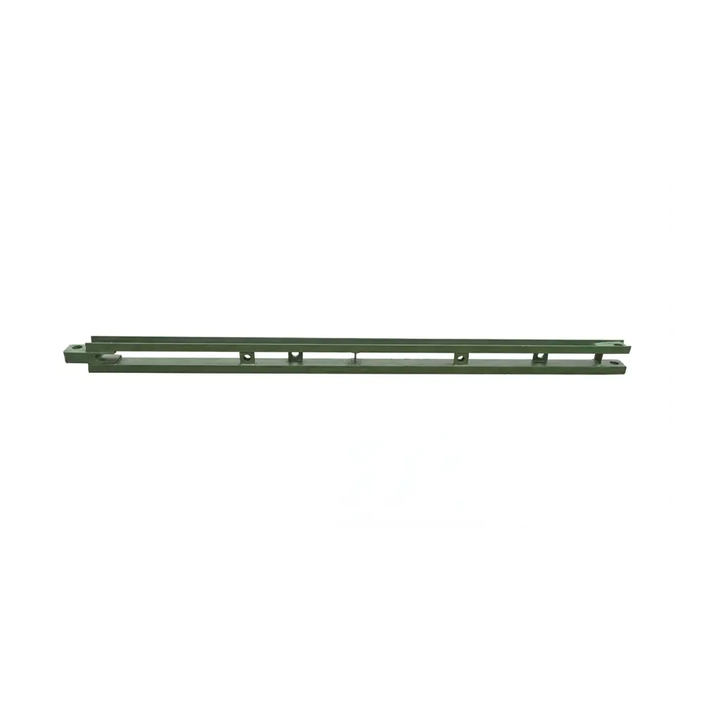
Modern bridge construction requires equipment that can support substantial structural loads while maintaining dimensional accuracy, installation efficiency, and long-term reliability. In projects involving pier construction, elevated platforms, bridge formwork, and climbing construction systems, the column head connection is one of the most important structural interfaces. It transfers loads, stabilizes the working platform, aligns the supporting members, and creates the connection between the permanent concrete column and the temporary or semi-permanent steel construction system.
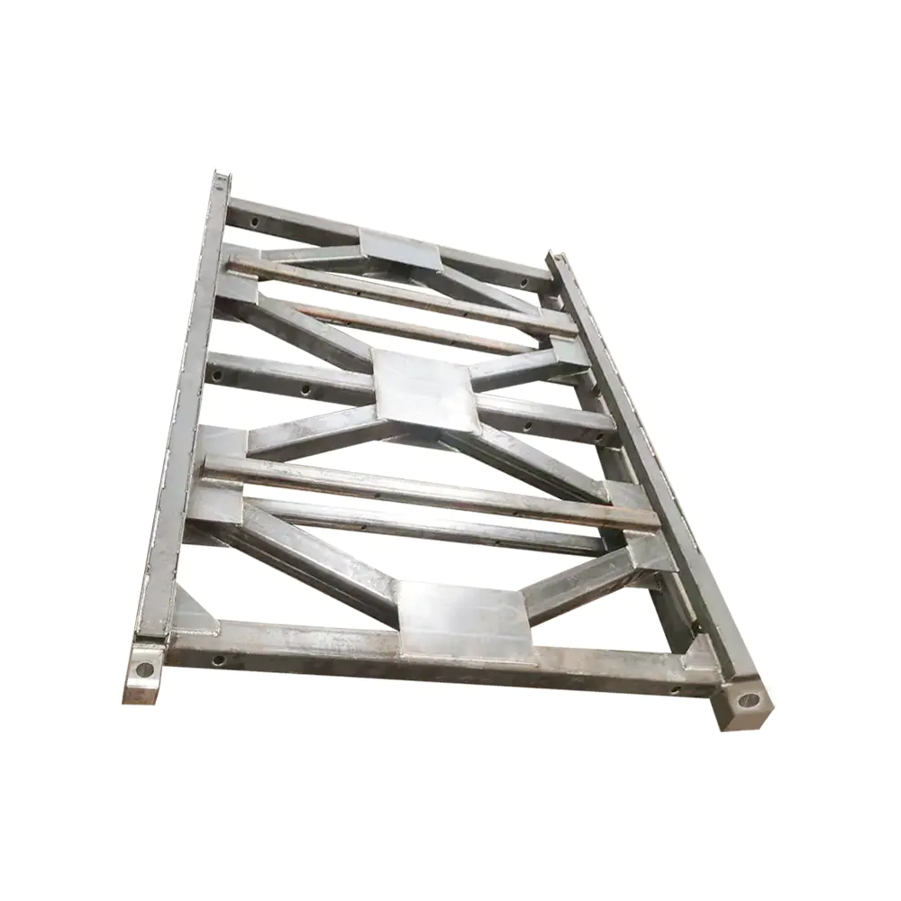
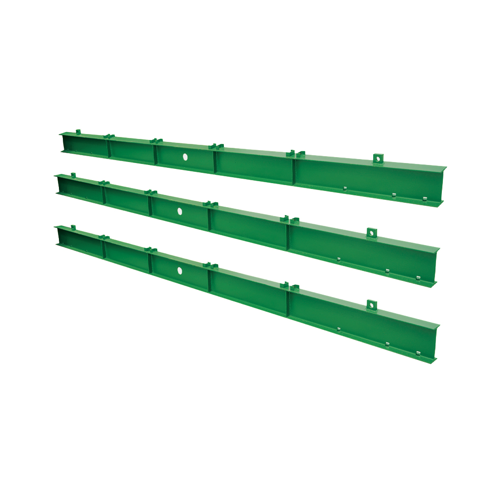
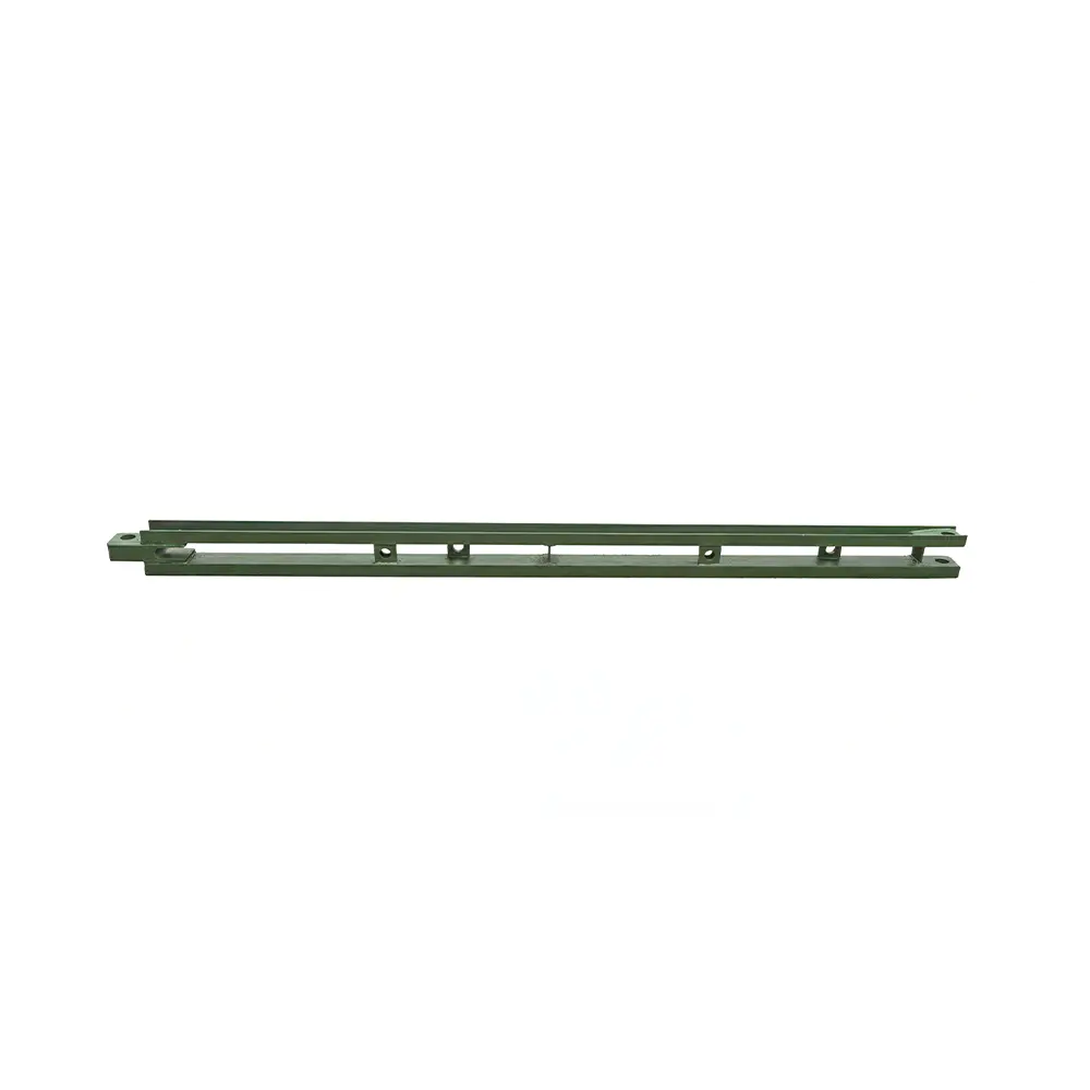
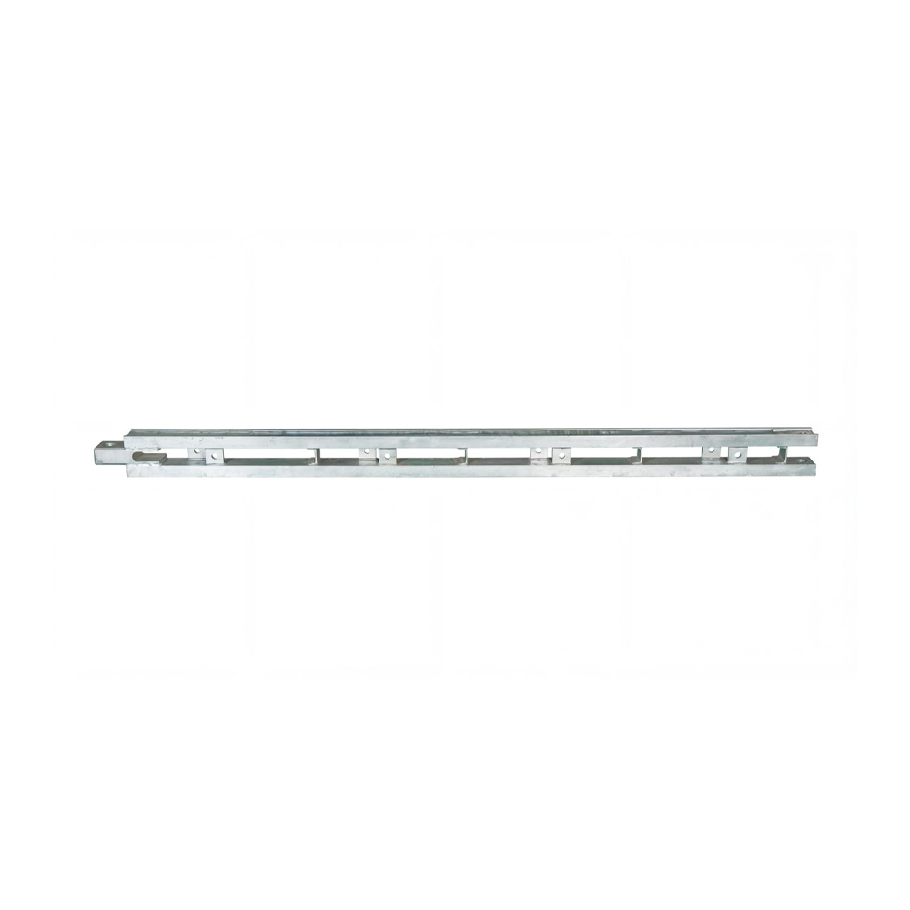
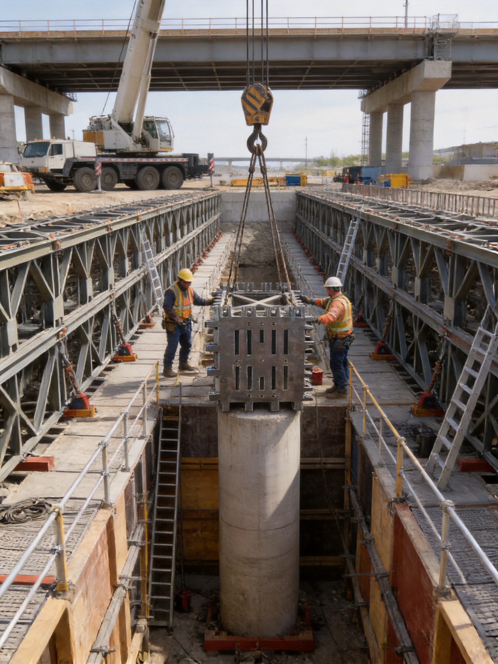
The ZK-Column Head Connector is engineered as the core foundation of a complete bump jacking formwork platform. It is designed to be positioned around or above a column head and to connect multiple rows of combined Bailey bridge panels. With its heavy steel plate bases, rectangular-tube vertical posts, welded construction, and large load-supporting geometry, the connector provides a stable and standardized interface for demanding bridge construction applications.
Manufactured from Q355B structural steel, the ZK-Column Head Connector combines high strength with practical fabrication characteristics. Its upper and lower bases are formed from 100 mm thick steel plates, while the vertical posts use 150 × 150 mm rectangular tubes. Each completed unit weighs approximately 2.5 tons, reflecting its robust structural design and ability to support large assembled platforms. Centered on the column head, each side can accommodate up to four rows of combined Bailey bridge panels simultaneously.
This article examines the connector’s design, manufacturing process, performance advantages, application value, installation considerations, and suitability for contractors seeking dependable bridge formwork and temporary works equipment.
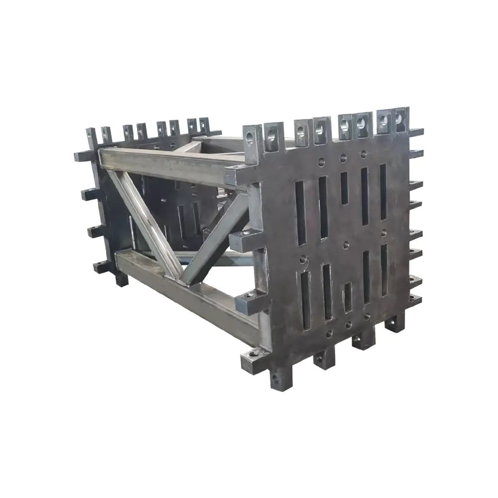
ZK-Column Head Connector
1. The Role of a Column Head Connector in Bridge Construction
In a bridge construction project, the column head is a critical transition zone between a vertical pier or column and the horizontal construction platform above it. This area often receives concentrated loads from formwork, reinforcement, workers, equipment, concrete placement operations, access systems, and temporary bridge panels. If the connection is weak, poorly aligned, or difficult to install, the entire working platform may experience instability or excessive deformation.
A column head connector addresses this challenge by creating a controlled and engineered support interface. Instead of relying on improvised steel members, scattered brackets, or inconsistent field welding, a dedicated connector provides a repeatable structural arrangement. The upper and lower bases define the primary load-transfer surfaces, while the vertical posts maintain the required spacing and alignment between these bases.
For a bump jacking formwork system, this function is especially important. The formwork system may need to move upward in stages as construction progresses. During each operating cycle, the support assembly must remain stable, accurately positioned, and capable of receiving changing loads. A rigid connector helps maintain the geometry of the platform and reduces the risk of movement at the column head.
The ZK-Column Head Connector is therefore more than a simple steel bracket. It serves as a central structural node that coordinates the connection of Bailey bridge panels, support members, and formwork components. By standardizing this node, it can simplify system design and make the overall construction platform more predictable.
1.1 Load Transfer and Structural Continuity
The connector is designed to distribute forces through its steel framework rather than concentrating all loads at a single small contact point. The substantial 100 mm thick upper and lower steel plates provide broad bearing surfaces. These plates help transfer vertical forces and resist local deformation at the connection area.
The 150 × 150 mm rectangular-tube posts form the vertical structural members between the bases. Their closed-section geometry gives them useful resistance to compression, bending, and torsional effects. In a multi-panel platform, loads may not always be perfectly symmetrical. Workers, equipment, materials, and formwork reactions can produce eccentric or uneven forces. A rigid rectangular-tube arrangement helps the connector maintain its shape under these practical conditions.
The welded assembly creates a unified steel component rather than a collection of loose pieces. This can reduce the number of individual joints that must be assembled in the field. It also allows the manufacturer to control critical dimensions during fabrication and inspection before the unit is delivered to the construction site.
1.2 A Central Interface for Bailey Bridge Panels
Bailey bridge panels are widely used as modular structural components because they are standardized, interchangeable, and adaptable to many temporary works applications. In addition to temporary bridge construction, they can serve as guide beams, support towers, gantry components, working platforms, and formwork support members.
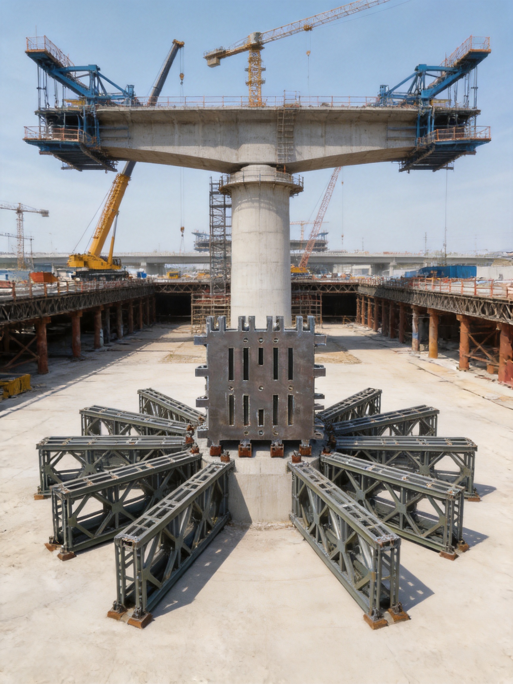
The ZK-Column Head Connector is configured to work with combined Bailey bridge panels arranged around the column head. Each side can accommodate up to four rows of panels simultaneously. This arrangement provides contractors with a practical way to create a high-capacity platform while retaining the modular characteristics of Bailey bridge construction.
The ability to connect several rows on each side is valuable when a project requires a broad working area or significant load capacity. Instead of using a small, isolated support, the connector becomes the central node of a larger assembled frame. The exact panel arrangement, bracing pattern, loading condition, and connection details must be verified by the project’s structural design team, but the connector provides the physical foundation for this configuration.
2. Product Construction and Technical Specifications
The structural configuration of the ZK-Column Head Connector is intentionally straightforward and heavy-duty. It uses large steel plates and rectangular-tube posts in a welded assembly. This approach supports manufacturing repeatability and provides a strong, visually inspectable product for bridge and formwork applications.
Technical Item |
Specification |
Product Type |
Column head connector for a bump jacking formwork system |
External Dimensions |
1340 × 1340 × 2234 mm |
Center Distance Dimensions |
305 × 3 × 2134 mm |
Upper and Lower Bases |
100 mm thick steel plates |
Vertical Posts |
150 × 150 mm rectangular tubes |
Steel Grade |
Q355B |
Approximate Unit Weight |
2.5 tons |
Panel Arrangement |
Up to four rows of combined Bailey bridge panels on each side, subject to engineering verification |
2.1 Heavy Base Plates
The 100 mm thick upper and lower bases are among the most important features of the product. Thick base plates provide structural stiffness at the top and bottom of the connector. They also create a solid interface for adjacent steel members and help resist local bearing pressure from connected components.
In temporary works, base plate performance is essential because the steel structure may be repeatedly loaded, unloaded, adjusted, or exposed to vibration during construction. A thin or inadequately supported plate may deform around bolt holes, bearing points, or welded attachments. The use of 100 mm thick plates gives the connector a substantial structural reserve and contributes to a more stable connection interface.
The thickness also supports more controlled fabrication. Large plates can be accurately cut, drilled, fitted, and welded according to a defined production drawing. When the same design is manufactured repeatedly, the base geometry can be standardized for use across multiple projects.
2.2 Rectangular-Tube Vertical Posts
The vertical posts are made from 150 × 150 mm rectangular tubes. Closed rectangular sections offer several benefits compared with simple flat bars or lightweight open sections. They provide a favorable ratio between structural capacity and overall dimensions, protect the internal section from direct exposure, and help maintain a clean connection layout.
Rectangular tubes are also suitable for assembling a compact vertical frame. Their flat faces simplify the positioning of plates, stiffeners, connection components, and other structural members. The resulting arrangement is practical for a product that must interface with multiple Bailey panel rows in a confined column-head area.
Because the posts are part of a welded unit, their alignment can be established during factory assembly rather than being created entirely at the construction site. This helps reduce the possibility of cumulative field errors, especially where several panels must be arranged symmetrically around the central column head.
2.3 Q355B Structural Steel
Q355B is a commonly used high-strength structural steel grade for fabricated steel structures. Its mechanical properties make it suitable for load-bearing components, bridge accessories, temporary works frames, and heavy steel assemblies. The material offers a useful combination of strength, weldability, and availability for industrial fabrication.
Material selection directly affects the service performance of a connector. A high-strength structural steel can help reduce the risk of yielding under design loads while allowing the component to remain within a manageable size. It also supports the production of robust products without requiring excessively complicated geometries.
As with any structural steel product, the final design capacity depends on the complete system, including connection details, welds, plate thickness, bracing, load eccentricity, foundation conditions, and installation configuration. Q355B provides the material foundation, but safe use still requires project-specific engineering verification.
3. Manufacturing Process and Quality Control
The performance of a heavy column head connector depends not only on the selected material and nominal dimensions but also on the quality of fabrication. Large welded components must be produced using controlled cutting, fitting, welding, inspection, correction, and finishing procedures. Manufacturing consistency is particularly important when the product is used as part of a modular construction system.
The manufacturer behind this product operates in the field of Bailey bridges, launching gantry systems, hanging baskets, pier formwork, bridge steel formwork, and related engineered steel structures. Its product experience provides a practical understanding of how modular bridge components must connect, carry loads, and perform in demanding construction environments.
3.1 Engineering Preparation
Production begins with a review of the product design, dimensions, connection requirements, material grade, and intended application. The external dimensions of 1340 × 1340 × 2234 mm and the stated center-distance arrangement must be translated into fabrication drawings that define plate profiles, post positions, weld locations, tolerances, and inspection points.
Engineering preparation is essential for a product that must connect to Bailey bridge panels. A small dimensional error at the column head may become more significant when several modular panels are assembled around the connector. Proper drawings help control the location of the posts, the relationship between the upper and lower bases, and the clearances needed for adjacent components.
Where a customer has a special project layout, additional design coordination may be required. The connector can form part of a broader solution involving panel combinations, support towers, working decks, jacking equipment, formwork, access arrangements, and temporary bracing. Early coordination helps ensure that the connector is compatible with the complete construction system.
3.2 Material Preparation and Cutting
Q355B steel plates and rectangular tubes are selected according to the approved fabrication requirements. The 100 mm base plates require accurate cutting and edge preparation. Heavy steel plate processing must account for plate flatness, thermal effects, handling requirements, and the need to maintain dimensional accuracy after welding.
The rectangular tubes must be cut to the specified lengths and prepared for their connections to the base plates. Accurate cutting is important because the post length directly influences the total height and alignment of the connector. Inconsistent post dimensions could cause the upper base to sit out of level or create difficulties when the connector is assembled with other structural components.
Industrial cutting equipment and controlled material handling can improve repeatability. The objective is to produce components that are dimensionally consistent before they enter the fitting and welding stage.
3.3 Assembly and Welding
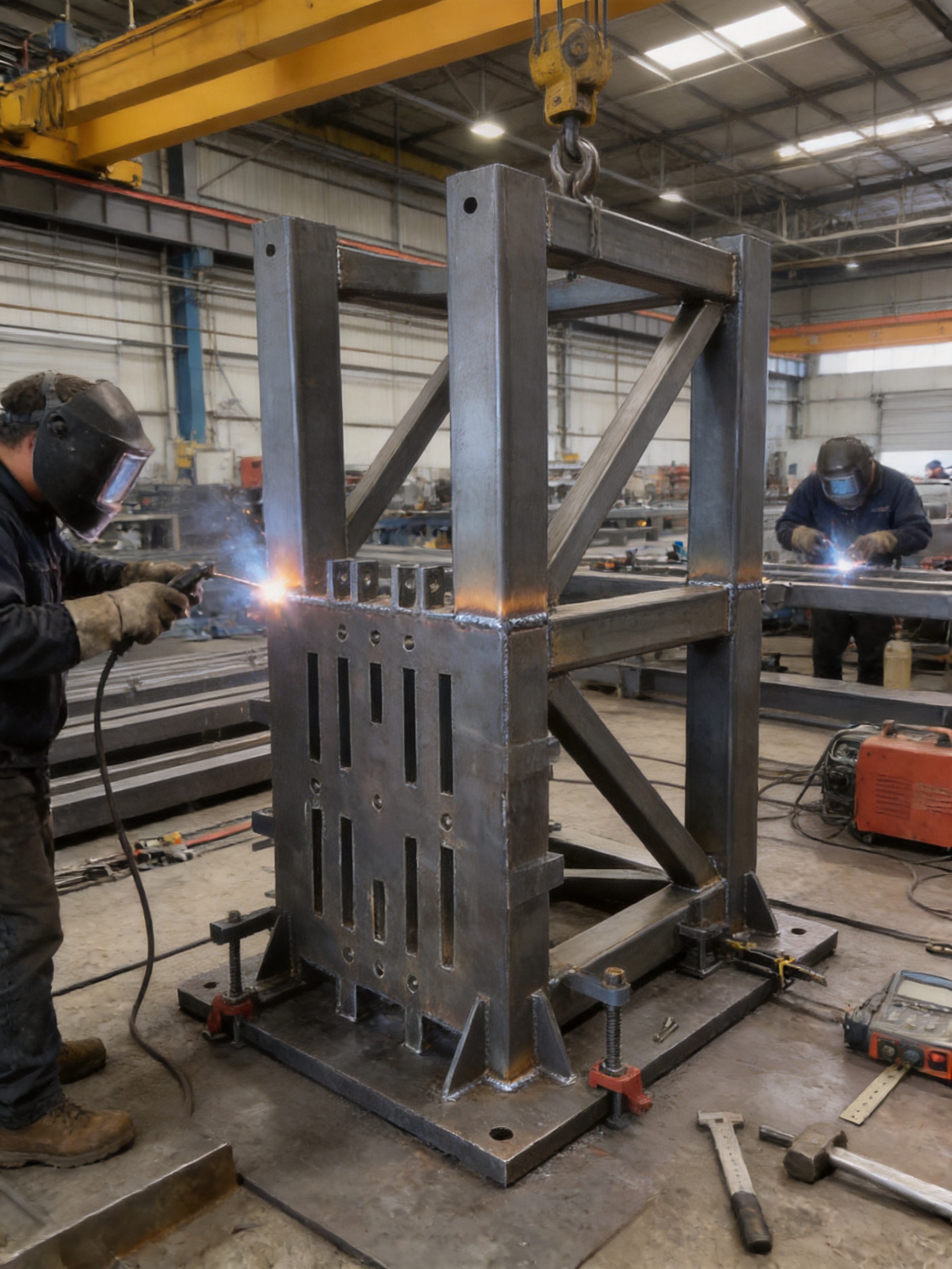
The product is assembled by welding. During this stage, the base plates and rectangular-tube posts are positioned in a controlled sequence. Jigs, fixtures, temporary supports, or measurement tools may be used to maintain the required geometry while welds are applied.
Welding procedure control is important for large structural assemblies. The welding process must provide adequate fusion, consistent penetration where required, and suitable strength for the design. Welders must also manage heat input to reduce distortion. Heavy plates and closed sections can experience thermal movement if welding is performed without a suitable sequence or restraint strategy.
A controlled welding sequence may involve alternating weld locations, balancing heat input, and allowing appropriate cooling between operations. These practices help preserve the squareness and alignment of the completed frame. Since the connector must support multiple rows of Bailey bridge panels, maintaining the geometry of the upper and lower bases is particularly important.
3.4 Dimensional Inspection
After welding, the connector should be inspected for overall dimensions, base alignment, post spacing, squareness, weld appearance, and connection compatibility. Inspection can include measurement of the external dimensions, center distances, plate flatness, verticality of the posts, and the relative position of the upper and lower bases.
Dimensional inspection helps identify distortion or fabrication deviations before the product is shipped. Correcting an issue at the factory is generally more efficient than attempting to modify a 2.5-ton welded assembly at a construction site.
Quality control also supports interchangeability. When multiple connectors or related modular components are supplied for one project, consistent dimensions allow them to be installed and arranged with fewer adjustments. This is one of the major advantages of using engineered modular steel products rather than individually fabricated field supports.
3.5 Surface Treatment and Delivery Preparation
Depending on the project specification, fabricated steel components may require surface cleaning, priming, painting, or other protective treatment. Surface treatment helps protect the steel during storage, transport, and construction. The selected coating system should reflect the expected exposure conditions and the customer’s maintenance requirements.
Because each unit weighs approximately 2.5 tons, delivery preparation must include suitable lifting points, transport supports, identification marks, and handling instructions. The product should be secured to prevent movement during transportation. Proper packaging and loading are especially important for large welded components that cannot be easily repacked at the site.
4. Advantages Compared with Conventional or Improvised Solutions
The ZK-Column Head Connector offers several practical advantages when compared with improvised steel supports, individually welded field assemblies, or undersized connection frames. These advantages relate to structural robustness, modular compatibility, installation organization, manufacturing consistency, and project planning.
4.1 A Purpose-Designed Structural Node
One of the main advantages is that the connector is designed specifically for a column head and a bump jacking formwork platform. Conventional supports may be assembled from miscellaneous beams, plates, angles, and temporary brackets. Although such arrangements can sometimes be made to work, they may require extensive site welding, repeated measurements, and additional reinforcement.
A purpose-designed connector establishes the primary geometry in advance. The manufacturer controls the relationship between the upper base, lower base, and vertical posts. This gives the contractor a defined starting point for the rest of the platform and reduces dependence on ad hoc field solutions.
4.2 High Structural Robustness
The combination of 100 mm thick base plates, 150 × 150 mm rectangular-tube posts, Q355B steel, and a 2.5-ton unit weight demonstrates a heavy-duty design philosophy. The connector is not intended to be a lightweight accessory. It is built to serve as a stable foundation for a substantial assembled structure.
Compared with lighter brackets or thin-plate assemblies, this configuration can provide improved resistance to local deformation and greater rigidity at the column head. This is valuable where the system must support several rows of Bailey panels and where the working platform is exposed to changing construction loads.
4.3 Compatibility with Modular Bailey Components
Bailey bridge panels are valued for their standardization and interchangeability. A connector that can accommodate multiple rows of these panels allows contractors to build a larger platform from familiar modular components. This reduces the need to develop a completely unique support frame for every project.
Modularity can also support resource management. Contractors that already own or regularly rent Bailey panels may be able to integrate those components into a bump jacking formwork arrangement, subject to design approval. The same family of modular steel members may be used for temporary bridges, guide beams, support towers, gantry structures, and formwork platforms.
4.4 Reduced Field Fabrication
Field welding and cutting can introduce schedule delays, quality variations, and safety risks. Weather, access limitations, restricted working space, and inconsistent site conditions can make field fabrication more difficult than factory production.
Because the ZK-Column Head Connector is assembled and welded before delivery, a significant part of the fabrication work is completed in a controlled workshop environment. The site team can focus on positioning, connection, inspection, and integration with the remaining platform rather than building the main column-head frame from raw materials.
4.5 Better Repeatability for Multiple Piers
Bridge projects often involve multiple piers with similar construction requirements. A standardized connector can be reused or replicated across these locations. Consistent geometry helps the project team establish repeatable installation procedures, inspection checklists, lifting plans, and assembly sequences.
Repeatability may also reduce training requirements. Once the crew understands the connection procedure for one unit, the same general method can be applied to other units, subject to project-specific conditions and safety controls.
4.6 Efficient Use of Available Space
The external dimensions of 1340 × 1340 × 2234 mm provide a compact but substantial structural envelope. The connector is designed to form a central support around the column head while allowing Bailey panels to extend outward on each side. This arrangement can help organize a high-capacity platform without spreading the primary support over an unnecessarily large footprint.
Efficient space use is important at bridge piers, where access may be restricted by water, traffic, adjacent structures, temporary roads, or existing foundations. A central connector gives designers a clear reference point for organizing the platform and associated access systems.
5. Applications in Bump Jacking Formwork Systems
Bump jacking formwork systems are used to support construction activities as work progresses vertically or through repeated staged operations. The system may include formwork panels, working decks, access platforms, lifting or jacking equipment, bracing, steel support members, and modular bridge components.
Within this arrangement, the ZK-Column Head Connector can function as a central support frame. It provides the connection point between the column head and the assembled Bailey bridge structure. The heavy bases create the primary support surfaces, while the rectangular-tube posts maintain the structural relationship between the two levels.
5.1 Pier and Column Construction
The connector is suitable for bridge pier and column construction where the formwork platform must be supported around a vertical concrete member. It can help create a working area for reinforcement placement, formwork adjustment, concrete operations, inspection, and access.
The exact arrangement depends on the pier geometry, column head dimensions, concrete sequence, platform height, and required working loads. Before installation, the project team should verify that the connector’s dimensions and bearing arrangement are compatible with the permanent structure and temporary works design.
5.2 Elevated Working Platforms
When combined with Bailey bridge panels and suitable decking, the connector can form part of an elevated working platform. Such a platform may be used for construction access, formwork support, reinforcement operations, inspection, or the temporary placement of approved equipment and materials.
Platform design must consider live loads, concentrated loads, horizontal forces, wind, vibration, impact, guardrails, toe boards, access ladders, and emergency arrangements. The connector provides the central structural node, but the complete platform must be checked as an integrated system.
5.3 Repeated Construction Cycles
In staged construction, the platform may be adjusted or moved as the column or pier rises. The connector’s standardized geometry can support a controlled operating sequence. Crews can inspect the connection, prepare the next movement, operate the jacking equipment according to the approved procedure, and verify the platform after each stage.
Movement operations should never rely solely on the apparent strength of the steel. They require a detailed method statement, coordinated communication, load monitoring where necessary, and confirmation that all temporary restraints and connections are ready for the next stage.
5.4 Integration with Other Steel Formwork Products
The manufacturer’s broader product range includes bridge steel formwork and pier formwork. This experience is valuable because the column head connector often needs to work alongside other fabricated steel products. Formwork panels, hanging baskets, support frames, launching systems, and modular bridge components must be considered together rather than as isolated products.
Integrated planning can improve the relationship between the connector and the formwork. It can also help identify access requirements, lifting points, adjustment zones, and potential interference before equipment reaches the site.
6. Installation and Site Coordination
Installation of a 2.5-ton welded connector requires careful planning. The product should be lifted using equipment with sufficient capacity and an appropriate safety margin. The lifting arrangement must account for the unit’s center of gravity, approved lifting points, sling angles, nearby structures, and the possibility of wind or restricted visibility.
6.1 Pre-Installation Checks
Before installation, the contractor should confirm the following items:
1. The delivered connector matches the approved drawings and project identification.
2. The steel surfaces, welds, base plates, and posts have no visible transport damage that could affect performance.
3. The column head and supporting surfaces are prepared, clean, and capable of receiving the intended loads.
4. The Bailey bridge panels and connection accessories are available and compatible with the approved arrangement.
5. Lifting equipment, temporary supports, access systems, and communication procedures are ready.
6. The installation sequence has been reviewed by the responsible engineering and safety personnel.
6.2 Positioning and Alignment
The connector must be positioned accurately around or over the column head according to the project drawings. Alignment is important because the Bailey panels on each side must connect without forcing, twisting, or creating unintended eccentricity.
Surveying tools may be used to check the central position, level, verticality, and orientation of the connector. Any required adjustment should be completed using approved methods. Uncontrolled site cutting, heating, drilling, or welding should not be carried out without engineering authorization because such modifications may affect the structural capacity or corrosion protection.
6.3 Bailey Panel Assembly
After the connector is positioned, Bailey panels can be assembled according to the approved configuration. The stated capacity of up to four rows on each side does not mean that every project should automatically use the maximum arrangement. The actual number of rows depends on the design loads, span, bracing, panel condition, connection details, and the capacity of the supporting structure.
Each panel connection should be checked for proper seating, pin or bolt installation, locking devices, alignment, and access for inspection. Temporary supports may be required during assembly until the complete bracing system is installed.
6.4 Inspection Before Loading
The platform should be inspected before personnel, formwork, materials, or equipment are placed on it. Inspection should verify that the connector is stable, all primary connections are complete, the Bailey panels are correctly assembled, the deck is secured, and guardrails and access systems are installed.
Loading should proceed gradually and in accordance with the approved construction plan. Avoiding sudden, concentrated, or unauthorized loads helps protect the temporary works system and makes it easier to identify unexpected movement or deformation.
7. Safety, Engineering, and Maintenance Considerations
A heavy-duty connector can contribute to a safe construction platform, but no structural component should be used outside its design conditions. The product must be incorporated into a project-specific temporary works design prepared by competent professionals.
7.1 Design Verification
Before use, the responsible engineer should verify the loads applied to the connector and the complete Bailey panel arrangement. This may include vertical dead loads, construction live loads, impact effects, wind loads, horizontal forces, jacking forces, eccentric loading, temporary conditions, and accidental load cases where applicable.
The design should also consider the supporting concrete column, bearing surfaces, connection hardware, welds, panel members, bracing, foundations, and any interaction with permanent structures. The connector’s nominal dimensions and material grade are important inputs, but they do not by themselves define a universal load rating.
7.2 Inspection During Use
Routine inspection should be carried out during the construction cycle. Inspectors should look for visible cracking, unusual deformation, loose or missing connection components, damaged coatings, corrosion, impact damage, and changes in alignment. Particular attention should be given to welded joints and areas where Bailey panels connect to the central frame.
After severe weather, an abnormal loading event, accidental impact, or unexpected movement, the platform should be checked before work resumes. Any suspected damage should be reported and assessed by qualified personnel.
7.3 Corrosion Protection
Steel construction equipment may be exposed to rain, humidity, concrete slurry, river environments, coastal air, dust, and repeated handling. Maintaining the protective coating helps preserve the service life of the connector. Damaged coating should be repaired according to the project’s coating specification.
Drainage and cleanliness are also important. Accumulated water, mud, or concrete residue can conceal defects and accelerate corrosion. Regular cleaning and access for inspection should be included in the maintenance plan.
7.4 Storage and Reuse
Because the connector is a robust fabricated steel unit, it may be suitable for reuse when it remains within its design condition and passes inspection. During storage, it should be placed on stable supports and protected from standing water, collision, and uncontrolled stacking.
Before reuse on a new project, the connector should be inspected for permanent deformation, weld damage, unauthorized modifications, corrosion loss, and compatibility with the new design. Reuse must be based on engineering approval rather than appearance alone.
8. Manufacturing and Service Strengths of the Supplier
The supplier is a China-based engineering company specializing in road and bridge supporting equipment. Established in 2017 and located in an industrial park in Zhenjiang, Jiangsu Province, the company has developed from a business focused on construction and industrial materials into a comprehensive enterprise involved in design, manufacturing, erection, leasing, and technical support.
Its product portfolio includes Bailey steel bridges, Type 321 Bailey truss sections, HD200 or Type 200 Bailey truss sections, triangular and diamond hanging baskets, bridge steel formwork, pier formwork, launching gantry systems, and other engineered steel structures. This broad product range gives the company experience across several related areas of bridge construction and temporary works.
8.1 Experience with Modular Steel Systems
The ZK-Column Head Connector benefits from the supplier’s understanding of modular bridge components. Bailey systems require careful attention to interchangeability, connection geometry, load paths, erection sequences, and field practicality. These considerations are directly relevant to a connector designed to support multiple Bailey panel rows.
Experience with modular components also supports customization. Contractors may require different panel combinations, platform widths, connection arrangements, or project-specific support details. A manufacturer familiar with standard and engineered steel structures can evaluate these requirements more effectively than a general fabrication shop with no bridge-system background.
8.2 Integrated Design and Fabrication Capability
The company provides design and system planning in addition to fabrication. This integrated approach can help customers coordinate the connector with other temporary works equipment. Instead of purchasing a single isolated steel component, a contractor can discuss the connector as part of a wider platform or formwork system.
Integrated support may be useful when the site has unusual geometry, restricted access, nonstandard loading, limited lifting capacity, or a need to combine several types of bridge equipment. Early technical communication can reduce later modifications and improve the efficiency of procurement and installation planning.
8.3 Erection, Leasing, and Technical Support
Services associated with erection and leasing can provide additional flexibility for contractors. Some projects require temporary equipment for a limited construction period rather than permanent ownership. Leasing may help reduce initial capital expenditure and simplify equipment allocation across multiple projects.
Technical support is also valuable for heavy steel temporary works. Customers may need assistance with product selection, panel combinations, transport planning, erection sequences, inspection requirements, or maintenance. A supplier that understands the complete construction process can contribute more than a company that only delivers raw steel components.
8.4 Quality-Oriented Business Approach
The company states a commitment to customer-first service, integrity, pragmatic operation, innovation-driven development, cooperation, advanced technology, and sustainable growth. These principles are relevant to structural steel products because quality depends on consistent communication, accurate documentation, controlled fabrication, and practical after-sales support.
For international contractors, supplier reliability includes more than product strength. It also includes responsiveness, production scheduling, packaging, documentation, export coordination, technical clarification, and the ability to support project changes. A manufacturer with experience in international bridge equipment can help reduce communication gaps during procurement.
9. Procurement Guidance for Contractors and Engineering Companies
When evaluating a column head connector, buyers should consider the complete application rather than comparing only the steel thickness or unit price. Important questions include the intended load, the number and arrangement of Bailey panels, the column-head dimensions, the available lifting equipment, the construction sequence, the environmental exposure, and the required reuse period.
9.1 Confirm Project Compatibility
The buyer should provide the supplier with relevant project information, including drawings, column geometry, platform requirements, Bailey panel type, expected loads, site restrictions, and delivery conditions. This allows the supplier to confirm whether the standard connector is suitable or whether additional engineering is needed.
9.2 Review Documentation
Procurement documentation may include general arrangement drawings, material information, welding and fabrication details, inspection records, coating requirements, lifting information, installation instructions, and maintenance recommendations. Clear documentation supports both construction planning and later inspection.
9.3 Consider the Complete Cost
The total project cost includes manufacturing, transport, lifting, installation, inspection, storage, maintenance, and possible reuse. A robust standardized connector may offer better overall value than a low-cost improvised solution if it reduces site labor, rework, delays, and safety risks.
Modular compatibility can also improve asset utilization. Bailey panels and related components may be used across several applications, including temporary bridges, emergency access routes, guide beams, support towers, gantry systems, and formwork platforms. This flexibility can increase the return on investment for contractors that maintain a modular steel equipment fleet.
10. Frequently Asked Questions
Q1: What is the primary purpose of the ZK-Column Head Connector?
The connector serves as the central structural foundation of a bump jacking formwork platform. It is positioned at the column head and provides an interface for assembling Bailey bridge panels and related steel support components.
Q2: What are the main dimensions of the connector?
The external dimensions are 1340 × 1340 × 2234 mm. The stated center-distance dimensions are 305 × 3 × 2134 mm. These dimensions should be checked against the project drawings before ordering or installation.
Q3: What material is used to manufacture the product?
The connector is manufactured from Q355B structural steel. The upper and lower bases are made from 100 mm thick steel plates, and the vertical posts are made from 150 × 150 mm rectangular tubes.
Q4: How much does one unit weigh?
One assembled unit weighs approximately 2.5 tons. The lifting plan must therefore include suitable cranes, slings, lifting points, ground conditions, and exclusion zones.
Q5: How many Bailey bridge panel rows can be connected?
Centered on the column head, each side can accommodate up to four rows of combined Bailey bridge panels. The actual number permitted on a project must be confirmed through structural design, taking account of loads, bracing, connection details, and the supporting conditions.
Q6: Is the connector supplied as a bolted kit or a welded assembly?
The main structure is assembled by welding before delivery. Bailey panels and associated modular components may use their own approved pins, bolts, or connection hardware according to the system design.
Q7: Can the product be customized?
Customization may be possible depending on the required dimensions, connection arrangement, Bailey panel type, loading conditions, and production schedule. Customers should provide project drawings and technical requirements for review before manufacturing.
Q8: Can the connector be reused?
It may be reusable if it remains within acceptable structural condition and is approved for the new application. Each reuse should include inspection for deformation, weld damage, corrosion, unauthorized modification, and compatibility with the new temporary works design.
Q9: Does the connector have a universal load rating?
No universal load rating should be assumed from the product dimensions alone. The allowable capacity depends on the complete system, including load direction, eccentricity, panel arrangement, bracing, connections, support conditions, and construction stage. A qualified engineer should verify the application.
Q10: What other products can be coordinated with the connector?
The connector can be considered alongside Bailey steel bridges, Type 321 and HD200 or Type 200 Bailey truss sections, bridge steel formwork, pier formwork, hanging baskets, launching gantry systems, support towers, and other engineered steel structures.
Q11: What should be checked after delivery?
The receiving team should verify the product identity, dimensions, visible condition, welds, base plates, rectangular-tube posts, coating, lifting points, and any supplied documentation. Damage or discrepancies should be reported before installation.
Q12: Why choose a purpose-built connector instead of fabricating one on site?
A factory-fabricated connector can provide better dimensional repeatability, controlled welding, reduced site fabrication, improved planning, and easier integration with modular Bailey components. It also reduces the need for uncontrolled cutting and welding in a restricted construction environment.
11. Conclusion
The ZK-Column Head Connector is a heavy-duty structural component developed for bump jacking formwork systems and related bridge construction platforms. Its principal advantages come from the combination of Q355B structural steel, 100 mm thick upper and lower bases, 150 × 150 mm rectangular-tube vertical posts, welded factory assembly, and compatibility with multiple rows of Bailey bridge panels.
With external dimensions of 1340 × 1340 × 2234 mm and an approximate unit weight of 2.5 tons, the connector is designed as a substantial central support rather than a lightweight accessory. Its role is to create a stable and repeatable interface at the column head, organize the surrounding modular steel system, and support the construction activities required for elevated bridge and pier work.
Compared with improvised field supports, the product offers improved standardization, structural robustness, modular compatibility, reduced site fabrication, and better repeatability across multiple construction locations. These advantages are reinforced by the supplier’s experience in Bailey bridges, bridge launching gantries, hanging baskets, pier formwork, bridge steel formwork, design, fabrication, erection, leasing, and technical support.
Nevertheless, the connector must always be used as part of a properly engineered temporary works system. The number of Bailey panel rows, applied loads, bracing configuration, connection details, lifting method, installation sequence, and inspection requirements must be confirmed for each project. When correctly designed and installed, the ZK-Column Head Connector can provide a dependable foundation for modular steel formwork platforms and help contractors achieve safer, more organized, and more efficient bridge construction operations.
References
1. Product technical information for the ZK-Column Head Connector, including dimensions, material, construction, and panel arrangement.
2. General principles of structural steel fabrication, welded assembly, dimensional inspection, and corrosion protection.
3. Engineering practice for Bailey bridge panels and modular temporary steel structures.
4. Guidance on temporary works design, construction-stage loading, lifting operations, and site inspection.
5. Manufacturer information concerning Bailey bridges, bridge launching gantry systems, hanging baskets, pier formwork, and bridge steel formwork.
6. General structural design principles for steel connection interfaces, load transfer, bracing, and construction platforms.


 Français
 Español
 عربى