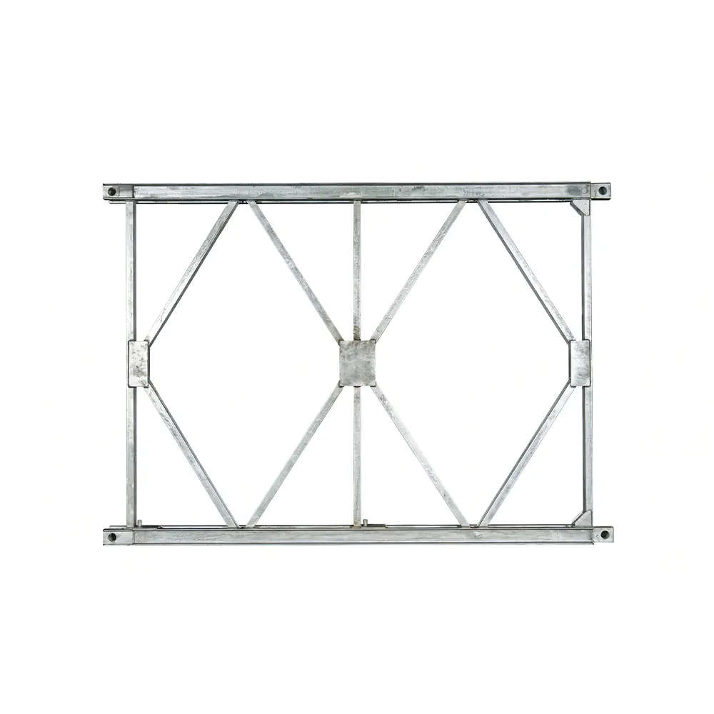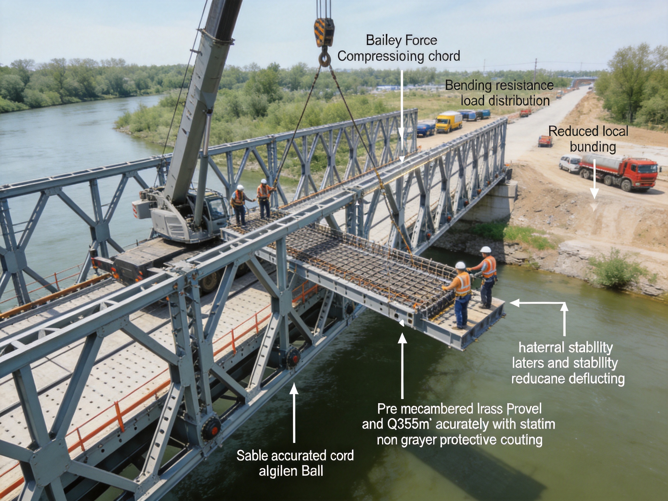
Bailey bridges are widely used where transportation infrastructure must be constructed quickly, adapted to changing site conditions, or restored after an emergency. Their modular steel truss configuration allows contractors and public agencies to assemble bridge systems from standardized components instead of waiting for a long, cast-in-place construction cycle. Within this modular structure, every chord, panel, bracing member, connection, and deck element contributes to the overall safety and serviceability of the bridge.
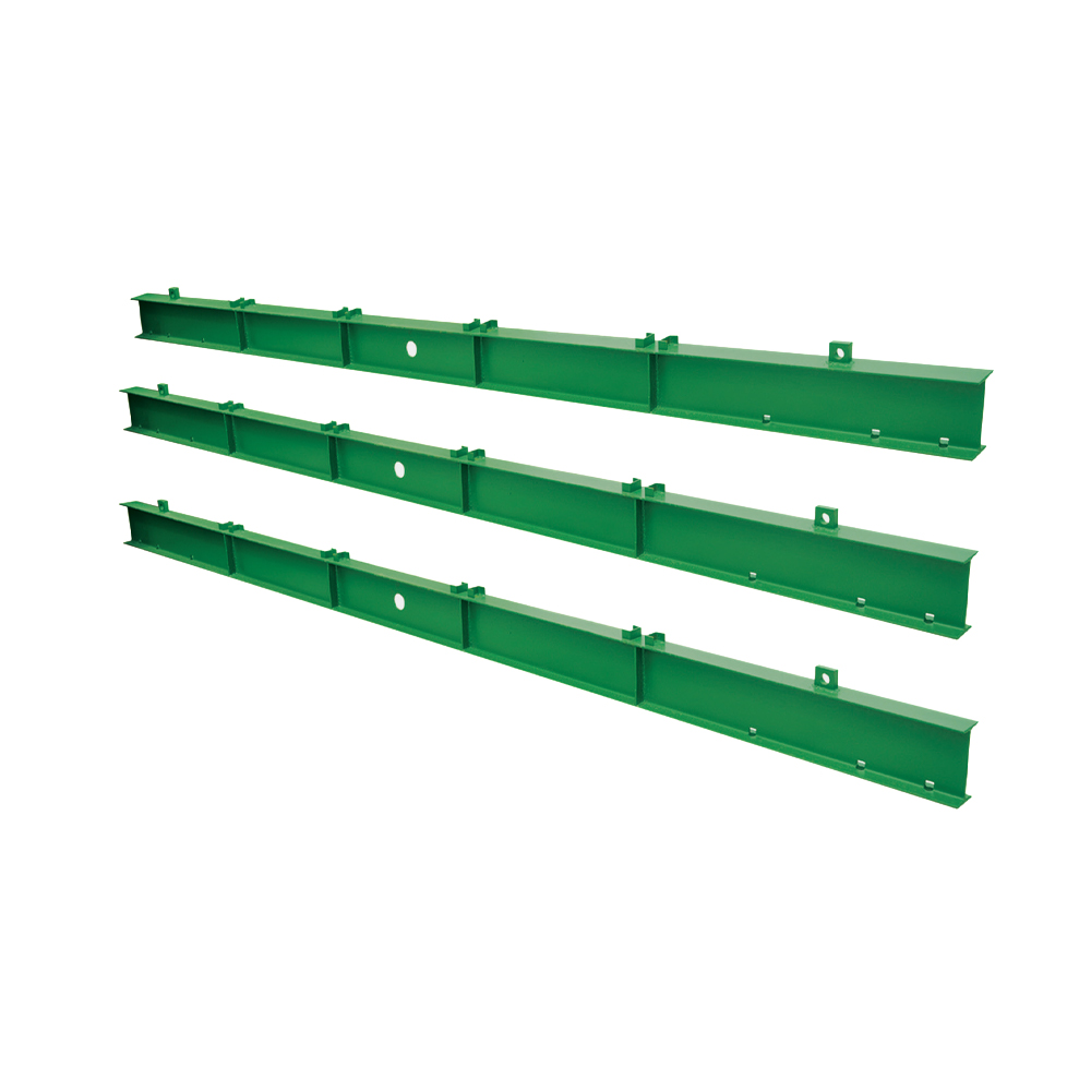
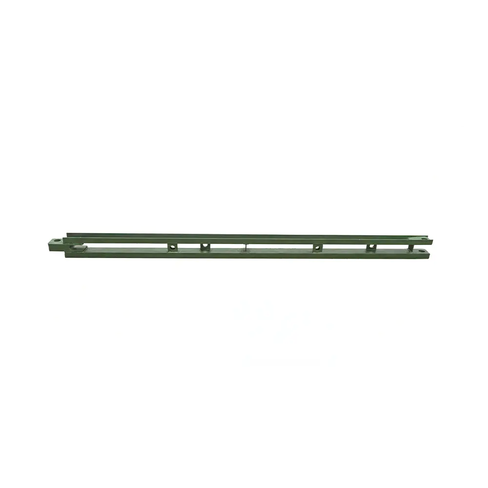
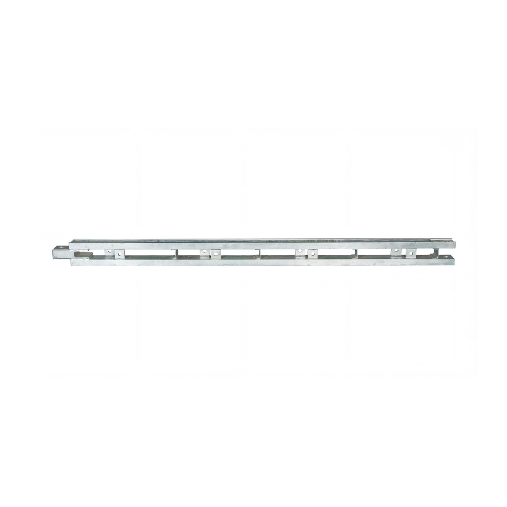
The upper reinforcing chord is a specialized component developed to improve the performance of the upper chord in a Bailey bridge or related prefabricated steel truss system. It is installed to reinforce the upper chord, particularly in regions where bending effects, axial compression, lateral instability, and local deformation may become critical. By adding a properly designed reinforcement member, the bridge system can achieve improved load distribution, greater resistance to local buckling, and better structural stability under demanding working conditions.
This article explains the function, design value, manufacturing characteristics, quality considerations, installation principles, and practical advantages of an upper reinforcing chord for Bailey bridges. It also examines why a purpose-designed Q355B component with external dimensions of 3115 × 1500 × 176 mm can provide a practical solution for contractors, bridge rental companies, infrastructure owners, and engineering organizations involved in temporary, emergency, semi-permanent, and fabricated steel bridge projects.
Understanding the Upper Reinforcing Chord
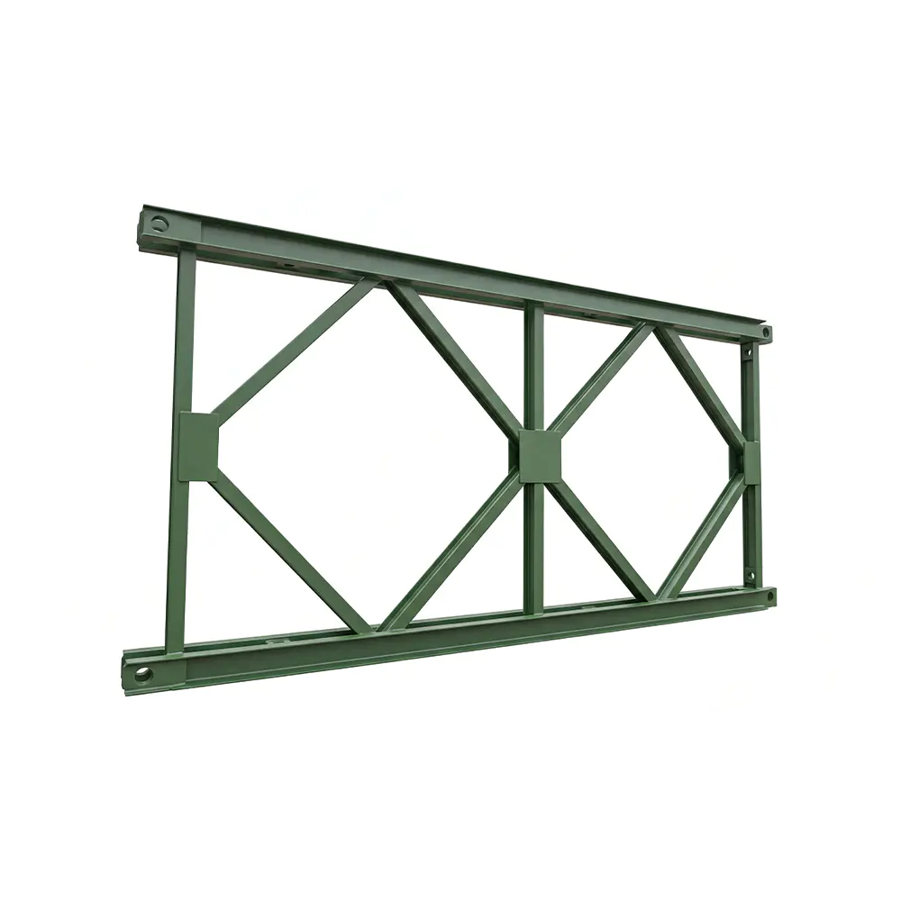
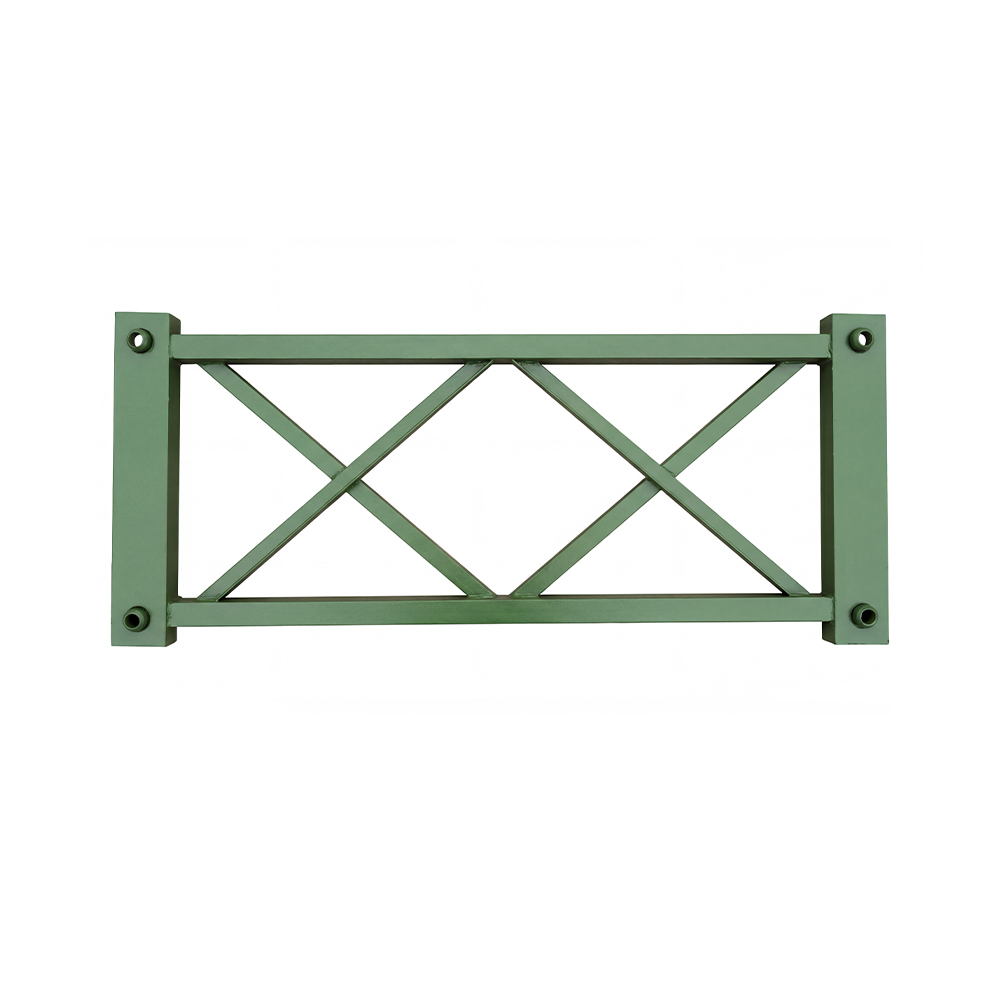
A Bailey bridge is generally assembled from prefabricated truss panels and connecting components. The upper chord is one of the principal longitudinal members of the truss. It transfers compression forces, participates in resisting bending moments, and works together with the lower chord, vertical members, diagonal members, transoms, bracing, and deck system to maintain the bridge’s structural geometry.
When a bridge carries traffic, construction equipment, stored materials, or other moving and static loads, the upper chord can experience a combination of axial compression and bending. These effects are influenced by the bridge span, support conditions, traffic arrangement, load position, wind, lateral restraint, erection sequence, uneven settlement, and the number of truss lines used in the bridge configuration.
Although the primary Bailey truss is designed to carry these forces, a reinforcing chord can provide additional structural support where the upper chord requires enhanced stiffness or greater resistance to instability. It helps the upper chord behave as part of a more robust load-resisting assembly. Rather than relying on a single member to resist all local effects, the reinforcement assists in distributing forces over a broader structural region.
The upper reinforcing chord is therefore not merely an additional piece of steel. It is an engineered component that supports the performance of the main truss and contributes to a more stable load path. Its value is particularly important in applications involving longer working spans, higher design loads, repeated traffic, demanding environmental conditions, or bridge configurations that require additional structural reserve.
Primary Structural Functions
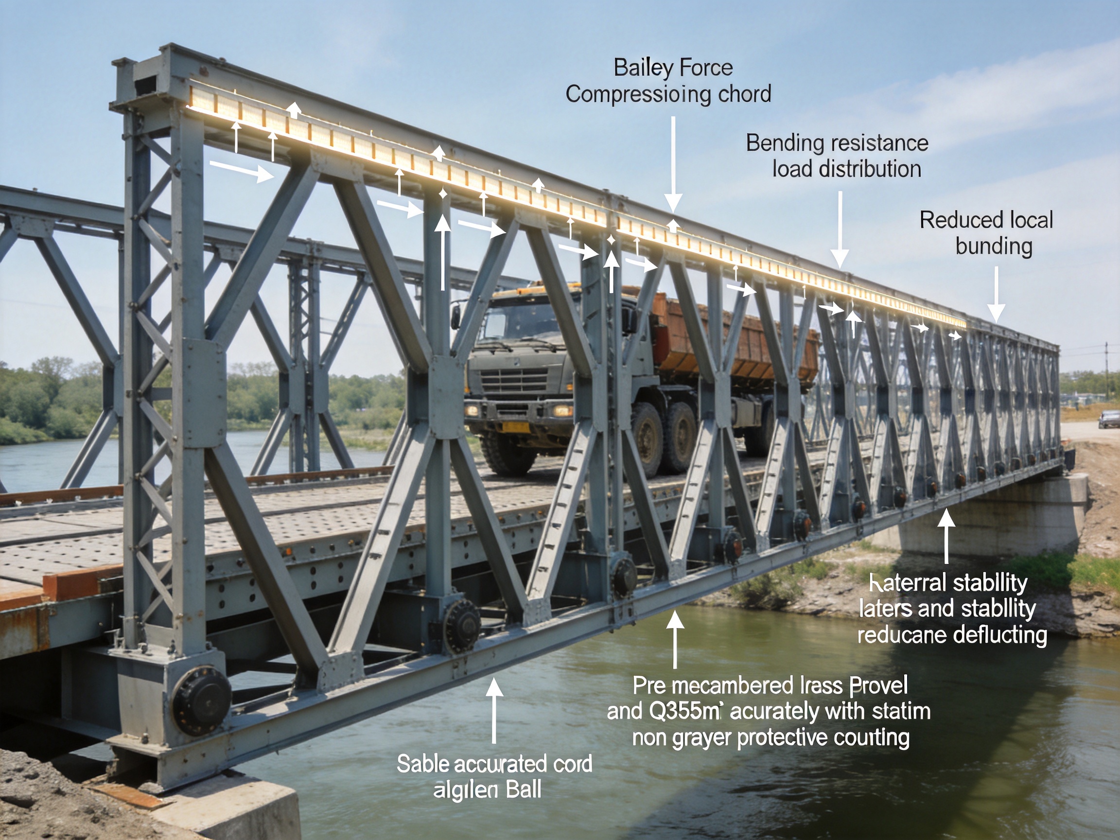
Improving Bending Resistance
The upper region of a truss may experience significant bending effects, especially near the middle of the span or in situations where the load is not evenly distributed between the truss lines. The reinforcing chord increases the effective stiffness of the upper chord assembly and helps the structure resist deformation caused by bending.
Improved bending resistance can help maintain the intended alignment of the bridge. This is important for the deck surface, vehicle movement, bearing behavior, and connection performance. Excessive deflection or local distortion can create secondary stresses, increase wear at connection points, and make inspection more difficult. By supporting the upper chord, the reinforcing member contributes to more predictable structural behavior.
Reducing the Risk of Local Buckling
Compression members are vulnerable to buckling when their effective length, slenderness, boundary conditions, or loading arrangement create an instability risk. Local buckling may occur in a plate, flange, web, or individual portion of a structural member before the entire bridge reaches its theoretical ultimate capacity.
An upper reinforcing chord helps suppress local deformation by increasing the resistance of the upper chord assembly to instability. It can provide additional restraint and improve the interaction between adjacent structural elements. The result is a stronger and more stable upper region, particularly in the mid-span area where bending and compression may act together.
Distributing Axial Pressure and Bending Moments
In a working bridge, load effects are transferred through a sequence of structural members and connections. If one member attracts a disproportionately high share of axial pressure or bending moment, localized stress concentrations may develop. The reinforcing chord helps distribute these effects more evenly across the upper chord region.
This improved distribution can reduce peak stresses and limit concentrated deformation around critical sections. It also supports the long-term serviceability of the bridge by helping the main structural members perform within their intended design range.
Supporting Structural Stability During Service
Bridge stability is affected by more than vertical vehicle loads. Wind, braking forces, lateral movement, eccentric loading, construction-stage conditions, and temporary support arrangements can all influence the response of a modular bridge. A properly installed upper reinforcing chord contributes to the stiffness and stability of the truss system under these combined conditions.
It is important to understand that reinforcement is one part of a complete bridge system. It does not replace engineering design, lateral bracing, adequate foundations, correct bearing installation, or proper connection control. Instead, it strengthens a critical region and works with the rest of the bridge to create a safer and more reliable assembly.
Product Specifications
The upper reinforcing chord described for this application is manufactured from Q355B structural steel and has external dimensions of 3115 × 1500 × 176 mm. These dimensions provide a substantial reinforcement assembly suitable for integration with compatible Bailey bridge truss systems and related prefabricated steel structures.
| Item |
Specification |
Engineering Significance |
| Product |
Upper reinforcing chord for Bailey bridge |
Reinforces the upper chord and supports truss stability |
| Category |
Pre-cambered Bailey truss |
Suitable for modular truss systems designed to manage working deflection |
| External dimensions |
3115 × 1500 × 176 mm |
Provides a defined geometric envelope for fabrication and installation |
| Material |
Q355B structural steel |
Provides a strong, weldable material base for engineered bridge components |
| Primary function |
Upper chord reinforcement |
Improves bending capacity and helps reduce local buckling risk |
Dimensions alone do not determine whether a component is suitable for a particular bridge. Compatibility must also be confirmed by reviewing the panel type, connection arrangement, truss spacing, design load, span, erection method, deck configuration, and applicable national or project standards. The component should be selected and installed as part of an engineered bridge system rather than treated as an isolated replacement part.
Why Q355B Steel Is Suitable for This Application
Q355B is a commonly used structural steel grade for demanding fabricated steelwork. Its strength level provides a useful balance between load-bearing performance, fabrication practicality, and availability. For bridge components exposed to axial forces, bending, vibration, and repeated loading, the selection of a reliable structural steel grade is essential.
The material provides a strong foundation for reinforcement components that must transfer significant forces through welded or connected assemblies. Its mechanical properties support the fabrication of plates, profiles, stiffened assemblies, and other bridge elements when the material is processed according to controlled manufacturing procedures.
Q355B is also suitable for many conventional fabrication operations, including cutting, forming, drilling, fit-up, and welding. However, material selection should always be supported by inspection documentation and project-specific requirements. Heat input, welding sequence, joint preparation, preheating, and post-weld inspection may affect the final performance of the component.
For outdoor bridge applications, corrosion protection is equally important. Q355B provides the structural substrate, while surface preparation and coating systems help protect the steel from moisture, salt, industrial pollutants, and repeated wet-dry cycles. Depending on the project, the component may be supplied with a suitable primer and protective coating or prepared for the customer’s specified corrosion protection system.
Pre-Cambered Truss Compatibility
The product is categorized as a pre-cambered Bailey truss component. Pre-cambering is used in bridge engineering to compensate, at least partially, for the expected deflection caused by permanent and service loads. It helps the completed bridge achieve a more suitable profile during operation and can improve deck smoothness and visual alignment.
An upper reinforcing chord must be manufactured with accurate geometry when it is used within a pre-cambered truss system. If dimensions or connection locations deviate significantly from the design, the reinforcement may not integrate correctly with the primary truss. Misalignment can create installation difficulties, force unintended stresses into connection points, or reduce the effectiveness of the intended load path.
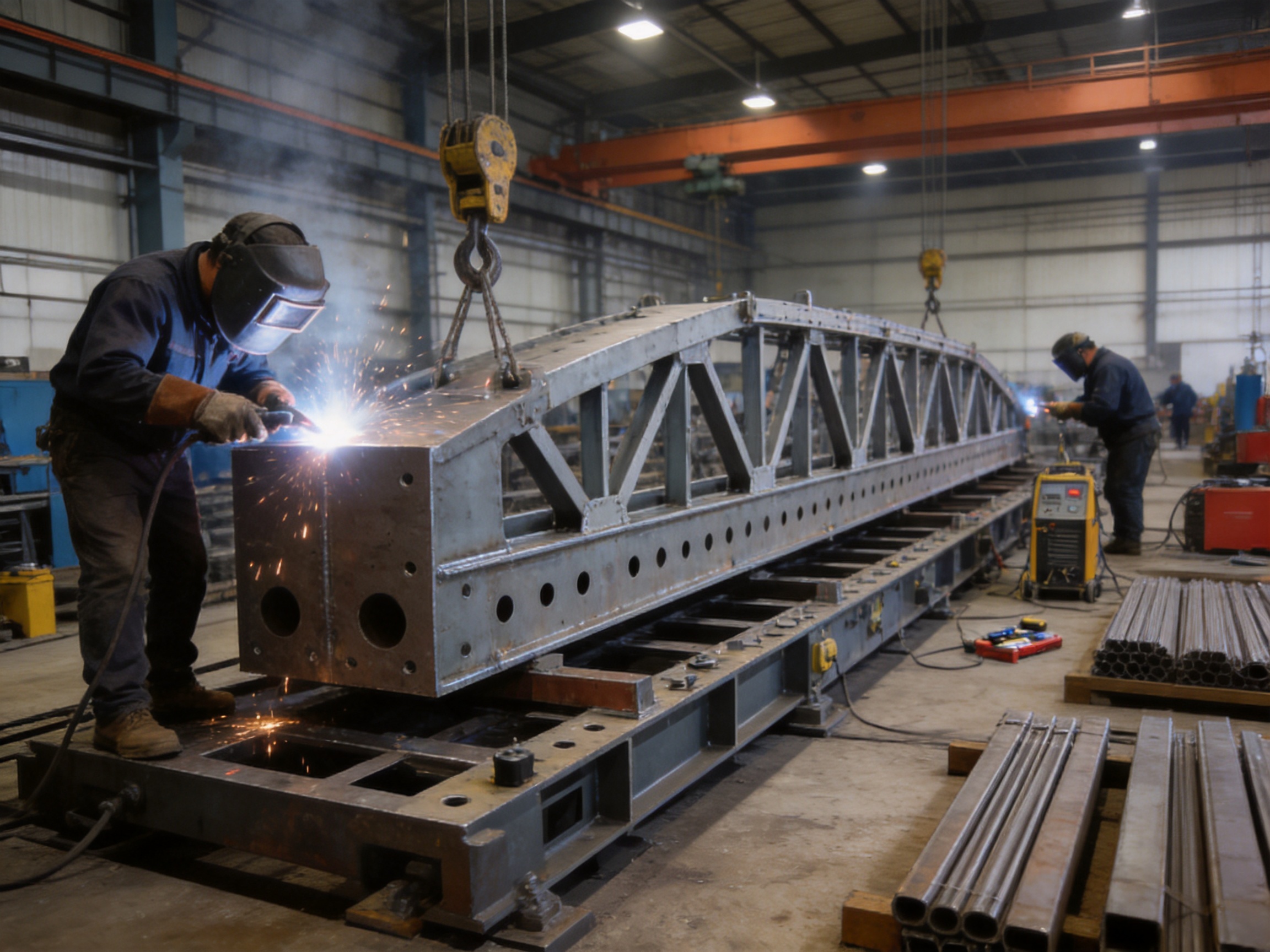
Controlled fabrication is therefore essential. The component should be produced using verified drawings, approved material, accurate cutting, stable jigs, controlled welding, and dimensional inspection. The manufacturing process should account for weld shrinkage and thermal distortion so that the finished product matches the required geometry.
Pre-cambered components also require careful storage and transportation. Improper stacking, unsupported lifting, or impact during handling may cause distortion before installation. Bridge contractors should inspect the component upon delivery and compare critical dimensions with the approved project documentation.
Manufacturing Process and Quality Control
Engineering Review and Production Planning
Manufacturing begins with a review of the component drawings, bridge configuration, material requirements, connection details, tolerances, coating system, and inspection plan. A professional manufacturer should identify potential fabrication risks before steel cutting begins. These risks may include difficult weld access, interference between connected members, excessive thermal distortion, lifting limitations, or incompatibility with the existing truss panels.
Production planning also determines how the component will be cut, assembled, welded, inspected, painted, marked, and packed. A clear manufacturing route improves consistency between batches and reduces the chance of errors caused by improvised workshop decisions.
Material Procurement and Identification
Steel plates and sections should be sourced according to the required Q355B specification. Material certificates, heat numbers, thickness records, and inspection documentation help maintain traceability. Each major material item should be identified during production so that the finished component can be linked to its source documentation.
Traceability is especially valuable for bridge components because the parts may be installed in temporary or semi-permanent infrastructure and later moved to another project. Proper records help owners and contractors confirm what materials were used, when the part was produced, and which inspections were completed.
Precision Cutting and Preparation
Accurate cutting establishes the basic geometry of the reinforcing chord. CNC plasma cutting, flame cutting, sawing, or other appropriate methods may be selected according to the thickness and shape of the steel. Cut edges should be inspected for excessive roughness, slag, cracks, notches, or other defects that could affect fit-up or fatigue performance.
Connection holes and interface features require particular attention. Hole position, diameter, spacing, and alignment should be controlled because these dimensions directly affect the ease of assembly and the distribution of forces through bolts, pins, or other connectors. Where holes are drilled or machined after cutting, the process should be managed to prevent ovality and unwanted deformation.
Assembly and Fit-Up
During fit-up, the individual plates and profiles are positioned in a controlled jig or on a verified assembly platform. Jigs help maintain length, width, diagonal alignment, connection spacing, and overall squareness. They also reduce the risk of cumulative dimensional errors across the component.
Temporary fixtures may be used to hold the assembly in position before final welding. Fit-up inspection should confirm that root gaps, edge preparation, contact surfaces, and member orientation meet the approved production requirements. Poor fit-up can increase weld stress, cause distortion, and create difficulties during bridge erection.
Controlled Welding
Welding is one of the most important stages in fabricating a reinforced steel bridge component. The welding procedure should define the welding process, consumables, joint preparation, preheating requirements, interpass temperature, weld sequence, and inspection method. Qualified welders and appropriate supervision help ensure that joints are produced consistently.
A balanced weld sequence can reduce angular distortion and residual stress. Where several welds are placed around a stiffened assembly, the order and direction of welding should be planned rather than left entirely to individual preference. After welding, visual inspection should identify undercut, overlap, porosity, incomplete fusion, excessive reinforcement, arc strikes, and other visible imperfections.
Non-destructive testing may be specified for critical welds. Depending on the design and project standard, this may include ultrasonic testing, magnetic particle testing, dye penetrant testing, or radiographic testing. The appropriate method should be chosen according to the joint type, material thickness, accessibility, and required level of assurance.
Dimensional Inspection
Dimensional control verifies that the finished upper reinforcing chord meets the required external dimensions and connection geometry. Inspectors may check total length, width, height, diagonals, straightness, flatness, hole locations, connection faces, and any camber-related features.
Inspection should take place at multiple stages rather than only after painting. Early checks can identify errors while correction remains practical. Final inspection confirms that welding, straightening, coating, and handling have not changed the component beyond acceptable tolerances.
Surface Treatment and Coating
Steel surfaces should be cleaned and prepared before protective coating is applied. Depending on the specified system, preparation may include abrasive blasting, mechanical cleaning, edge treatment, and removal of oil, rust, weld spatter, and other contaminants.
The coating system should be selected for the intended environment. Bridges installed in humid areas, coastal regions, industrial zones, or locations exposed to deicing salts may require enhanced corrosion protection. Coating thickness, adhesion, curing time, and visual coverage should be checked and recorded.
Marking, Packing, and Dispatch
Clear identification supports efficient site assembly. Each component can be marked with a part number, batch or production reference, orientation indicator, lifting information, and other project-specific data. Proper marking reduces the possibility of installing a component in the wrong location or orientation.
During packing, contact surfaces and connection holes should be protected from impact and contamination. Lifting points should be used according to the approved handling plan. Components should be supported adequately during transport to prevent bending, twisting, or coating damage.
Advantages Compared with Basic or Poorly Controlled Alternatives
Purpose-Designed Reinforcement
One important advantage of a dedicated upper reinforcing chord is that it is designed for the specific function of strengthening the upper chord. Improvised reinforcement made from unrelated steel sections may appear economical, but it can introduce uncertain load paths, connection incompatibility, uneven stiffness, and installation risks.
A purpose-designed component provides a clearer relationship between its geometry and its structural role. This makes it easier for engineers to review, for manufacturers to produce, and for contractors to install. It also supports more consistent performance when multiple bridge units are assembled on different projects.
Improved Geometric Consistency
Modular bridge systems depend on interchangeability. Components manufactured with controlled dimensions are more likely to align correctly with standard panels, connectors, braces, and deck systems. Better geometric consistency can reduce field modification, drilling, forced alignment, and unplanned welding at the construction site.
Compared with products manufactured without reliable jigs or inspection procedures, a precision-controlled reinforcing chord can help shorten installation time and reduce the risk of assembly-related defects.
Higher Confidence in Material and Weld Quality
Material traceability, controlled welding, and documented inspection provide a stronger quality foundation than an unverified component. This is particularly important when the reinforcement is used in a bridge carrying public traffic or heavy construction vehicles.
Reliable manufacturing does not eliminate the need for engineering verification, but it gives the design team better information about the actual component. That improves confidence in calculations, inspection planning, maintenance decisions, and future reuse.
Better Support for Reuse and Rental Operations
Bailey bridge components are often moved between projects. A robust upper reinforcing chord that is correctly marked, protected, inspected, and stored can be reused more efficiently. Standardized manufacturing supports inventory management and makes it easier for bridge rental companies to identify compatible components.
Reusable components also support sustainability by reducing the need to fabricate new steel for every project. However, reuse must be accompanied by condition assessment. Components should be checked for corrosion, cracks, permanent deformation, damaged holes, weld defects, and unauthorized modifications before being returned to service.
Adaptability to Multiple Infrastructure Applications
Although the upper reinforcing chord is intended for Bailey bridge truss systems, the engineering principles behind the product are relevant to several prefabricated steel structures. Modular bridge components may be used in temporary road crossings, construction access bridges, emergency detours, industrial transport routes, water conservancy works, railway support projects, and site logistics systems.
The exact application depends on the design and compatibility assessment. The key advantage is that a standardized reinforcement component can be incorporated into a broader range of engineered modular structures without requiring the entire bridge to be redesigned from the beginning.
Company Manufacturing and Engineering Strengths
Zhenjiang Jinhao Road & Bridge Supporting Engineering Co., Ltd. operates from an industrial area in Zhenjiang, Jiangsu Province, China. Established in 2017, the company has developed from a supplier of construction and industrial materials into an enterprise involved in the design, manufacturing, erection, and leasing of bridge-related steel systems.
Its product range includes Bailey steel bridges, Type 321 Bailey truss sections, HD200 or Type 200 Bailey truss sections, bridge launching gantry systems, hanging baskets, pier formwork, bridge steel formwork, and other engineered steel structures. This product breadth is valuable because a bridge project often requires more than one isolated component. Customers may need trusses, erection equipment, formwork, support structures, technical coordination, and field assistance from a connected supply chain.
The company’s experience with bridge systems supports a practical understanding of how components behave beyond the fabrication workshop. Design, manufacturing, erection, and leasing experience can provide useful feedback about connection access, transport limitations, field alignment, coating durability, maintenance, and the realities of repeated assembly.
Integrated Design and Fabrication Capability
An integrated design and manufacturing approach can reduce communication gaps between engineering and production teams. When drawings are developed with fabrication and erection in mind, the final component is more likely to be practical to manufacture and install.
For an upper reinforcing chord, this may include consideration of lifting points, connection access, weld accessibility, component orientation, handling weight, storage requirements, and inspection locations. These details are often as important to project success as the basic strength calculation.
Support for Customized Projects
Modular bridge projects frequently differ in span, load, width, deck type, traffic category, site access, foundation condition, and environmental exposure. A supplier with design and fabrication experience can review project information and help determine whether standard components are suitable or whether modifications are required.
Customization may involve dimensions, connection details, coating systems, component markings, packaging, delivery sequences, or technical documentation. Any structural modification should be reviewed and approved by qualified engineers before fabrication.
Experience with Erection and Field Requirements
Bridge components are successful only when they can be assembled safely and accurately at the project site. Experience with erection provides insight into temporary supports, launching procedures, lifting plans, bracing requirements, pin and bolt installation, bearing preparation, and alignment checks.
This practical knowledge can help prevent common problems such as insufficient working space, inaccessible bolts, incorrect component orientation, inadequate temporary restraint, or unsuitable lifting arrangements. It also allows the supplier to provide more useful technical support to contractors and project owners.
Quality-Oriented Production
A quality-oriented manufacturer should treat product quality as a complete process rather than a final visual inspection. It begins with design review and material selection, continues through cutting, assembly, welding, dimensional inspection, surface treatment, packing, and dispatch, and extends to technical communication during installation.
For bridge reinforcement components, quality management should focus on strength, geometry, compatibility, corrosion protection, traceability, and safe handling. These factors work together to determine whether the component will deliver reliable service.
Applications in Bridge Engineering
Temporary and Emergency Bridges
Emergency bridge projects require rapid mobilization and dependable components. Floods, earthquakes, landslides, damaged culverts, construction incidents, or severe weather may interrupt an existing route. A modular Bailey bridge can restore access more rapidly than a conventional permanent bridge, provided that foundations, approach roads, traffic controls, and structural design are properly prepared.
The upper reinforcing chord can support the structural reliability of the truss during this temporary service period. It may be particularly valuable where the bridge must carry construction vehicles, relief equipment, supply trucks, or repeated traffic over a significant span.
Construction Access Bridges
Construction projects often need temporary crossings over rivers, drainage channels, excavations, rail lines, roads, or uneven terrain. A modular steel bridge can provide access for cranes, concrete trucks, earthmoving equipment, and material deliveries.
Because construction traffic may produce concentrated wheel loads and frequent braking or acceleration, the bridge design should account for more than a simple uniform load. Reinforcement of the upper chord can be considered as part of a complete system designed for the expected vehicle class, traffic frequency, and operating duration.
Municipal and Water Conservancy Projects
Municipal works and water conservancy projects frequently involve changing site conditions and restricted construction windows. Temporary bridges may be used to maintain local traffic while a permanent bridge is repaired or replaced. They may also provide access across irrigation channels, flood control works, reservoirs, and construction zones.
In these environments, corrosion protection, drainage, inspection access, and foundation stability require careful attention. The upper reinforcing chord contributes to the truss system, while the overall project must address environmental exposure and operational safety.
Railway and Industrial Infrastructure
Railway construction, industrial plants, mines, ports, and logistics facilities may require heavy-duty temporary crossings and support structures. Modular steel systems can be adapted for material handling, construction access, temporary production routes, and equipment movement.
These applications often involve unusual load configurations or restricted site access. The reinforcement component should be selected only after the actual wheel loads, equipment dimensions, impact factors, clearance requirements, and operating conditions have been reviewed by the responsible engineering team.
Installation Principles
The installation of an upper reinforcing chord should follow approved drawings and an erection method statement. Before assembly begins, the contractor should confirm the condition and identification of all parts, verify the foundation and bearing positions, and establish safe lifting and access procedures.
The bridge panels and primary truss members should be aligned before the reinforcing chord is connected. Connection surfaces must be clean, free from excessive coating buildup, and free from damage that could prevent full engagement. Pins, bolts, washers, and other connecting hardware should match the specified type and size.
Installation crews should avoid forcing a component into position by excessive impact or uncontrolled mechanical pulling. If the component does not align, the cause should be investigated. Possible causes include incorrect orientation, damaged members, foundation movement, accumulated dimensional tolerance, or an unsuitable erection sequence.
Temporary bracing may be required during erection, especially before the complete truss and deck system has developed its intended stability. The bridge should not be opened to traffic until the upper reinforcing chord, lateral bracing, deck, bearings, connections, and safety features have been checked and accepted.
Inspection and Maintenance
Routine inspection helps preserve the performance of the upper reinforcing chord and the entire Bailey bridge. Inspection intervals should reflect the bridge’s traffic level, environmental exposure, importance, and expected service duration.
Inspectors should examine the component for corrosion, coating loss, dents, local buckling, permanent deformation, cracks, loose fasteners, damaged holes, weld defects, and contact wear. Particular attention should be given to connection regions because repeated movement or poor fit-up may cause fretting, hole enlargement, or localized damage.
After unusual events such as vehicle impact, flooding, foundation settlement, excessive overload, fire, or strong wind, an additional inspection should be completed before the bridge returns to normal service. If deformation or cracking is found, the affected area should be isolated and reviewed by a qualified engineer.
Maintenance may include cleaning, touch-up coating, tightening or replacing approved fasteners, correcting drainage problems, removing debris, and repairing minor protective coating damage. Structural repairs, welding, drilling, cutting, or modification should not be carried out without engineering approval because unauthorized changes may alter the load path and invalidate the original design assumptions.
Safety and Design Considerations
An upper reinforcing chord can improve the capacity and stability of a Bailey bridge, but it must be integrated into a complete structural design. The responsible engineer should review span length, bridge width, traffic load, truss arrangement, deck type, camber, lateral bracing, wind loading, impact effects, fatigue considerations, foundation conditions, and the intended service period.
Temporary bridges are not automatically low-risk structures. Their rapid installation can create pressure to shorten design and inspection activities, but the same structural principles that apply to permanent bridges remain important. A temporary bridge must still provide a defined load path, adequate stability, secure connections, safe access, and suitable protection against foreseeable environmental and operational hazards.
Load limits should be clearly posted and enforced. Traffic control should prevent vehicles from exceeding the design weight, speed, clearance, or lane arrangement. Where heavy or unusual vehicles must cross, a specific assessment may be required before passage.
Procurement Guidance for International Buyers
When purchasing an upper reinforcing chord, buyers should provide sufficient technical information to confirm compatibility. Useful information includes the existing Bailey bridge type, truss panel dimensions, span, bridge width, design load, deck arrangement, connection method, number of truss lines, required quantity, coating specification, delivery location, and applicable standards.
Buyers should request dimensional drawings, material information, inspection documents, coating details, packing information, and installation guidance. If the product is intended for reuse, the buyer should also clarify the expected number of assembly cycles and the inspection procedure after dismantling.
It is also important to distinguish between a component supplier and a system-oriented engineering manufacturer. A supplier that can support truss sections, launching systems, formwork, erection services, and customized fabrication may provide better coordination for complex projects. This can reduce the number of interfaces between separate vendors and simplify technical communication.
Before placing an order, the buyer should confirm production lead time, inspection arrangements, export packing, shipping dimensions, lifting requirements, spare parts, documentation language, after-sales support, and responsibility for design approval. These commercial and technical details can have a substantial impact on the total project cost.
Environmental and Economic Benefits
Modular steel bridges can offer economic advantages because they are assembled from reusable components and can reduce construction time. A shorter installation period may limit traffic disruption, reduce temporary roadworks, and lower the amount of labor required at the site.
Reinforcement components that extend the practical service life of truss systems can also improve asset utilization. Bridge owners, rental companies, and contractors may reuse the same components across multiple projects, provided that inspections confirm their continued suitability.
Steel is also recyclable at the end of its service life. Responsible fabrication, efficient material planning, repairable coatings, and controlled reuse can reduce waste. The environmental performance of a bridge system depends on the complete life cycle, including manufacturing energy, transport distance, erection method, maintenance, reuse, and recycling.
How the Component Supports Project Efficiency
The upper reinforcing chord contributes to project efficiency in several ways. First, it is prefabricated, which moves much of the work from a difficult site environment into a controlled manufacturing facility. Factory production can provide more consistent access to equipment, inspection tools, welding procedures, and material handling systems.
Second, standardized dimensions help integrate the component into a modular bridge configuration. This reduces the need for site fabrication and allows the installation team to focus on assembly, alignment, connection, and inspection.
Third, a purpose-designed reinforcement solution can reduce uncertainty during engineering review. Instead of relying on improvised field strengthening, the project team can evaluate a defined component with known dimensions, material, and manufacturing records.
Finally, the component can support a broader bridge supply strategy. When combined with compatible Bailey truss panels, bridge launching equipment, steel formwork, and technical services, it forms part of an integrated solution for rapid infrastructure construction.
Q&A
What is an upper reinforcing chord for a Bailey bridge?
It is a prefabricated structural reinforcement component installed at or around the upper chord of a Bailey bridge truss. Its primary purpose is to improve bending resistance, distribute axial pressure and bending moments, and reduce the likelihood of local buckling or deformation in the upper chord region.
What are the listed dimensions of this product?
The listed external dimensions are 3115 × 1500 × 176 mm. These dimensions should be compared with the bridge drawings and connection arrangement before ordering or installation.
What material is used?
The component is made from Q355B structural steel. Material certificates and project-specific inspection documents should be reviewed to confirm compliance with the required specification.
Can the component be used with every Bailey bridge?
No. Bailey bridges vary in panel type, truss arrangement, connection details, width, load rating, and design configuration. Compatibility must be confirmed through engineering drawings and a review of the existing bridge system.
Does the reinforcing chord replace the main upper chord?
It is generally intended to reinforce the existing upper chord rather than replace the primary truss member. The actual role depends on the approved structural design and connection arrangement.
Why is local buckling control important?
Local buckling can cause a portion of a compression member to deform before the full bridge reaches its expected capacity. Controlling local instability helps maintain the intended load path and reduces the risk of concentrated deformation and connection problems.
Is the component suitable for temporary bridges?
It can be used in temporary, emergency, construction access, and semi-permanent bridge systems when it is compatible with the design and approved by the responsible engineering team. Temporary use does not remove the need for structural calculations, inspection, and safe traffic control.
What should be checked before installation?
The contractor should check component identification, dimensions, coating condition, connection holes, welds, lifting points, orientation, bridge panel compatibility, bearing positions, and the condition of all related structural members.
How does manufacturing quality affect performance?
Accurate cutting, controlled fit-up, qualified welding, dimensional inspection, surface treatment, and traceability help ensure that the component matches the design. Poor manufacturing control can create misalignment, connection difficulties, stress concentrations, and reduced durability.
Can the component be reused?
Potentially, yes. Reuse depends on the component’s condition, service history, corrosion level, deformation, weld condition, connection-hole wear, and the requirements of the next project. An inspection should be completed before reuse.
What type of company can supply this component?
A bridge engineering manufacturer with design, fabrication, erection, and leasing experience can provide more complete support than a general steel trader. Such a supplier may also coordinate Bailey trusses, launching gantries, steel formwork, and technical services.
Is coating included automatically?
Coating arrangements should be confirmed in the purchase contract. The required system may vary according to the environment, project specification, transport method, and customer preference.
Can the component be customized?
Customization may be possible for dimensions, connection details, coating, markings, packaging, or project documentation. Structural modifications should be reviewed and approved before production.
Conclusion
The upper reinforcing chord is a valuable component for improving the performance of prefabricated Bailey bridge truss systems. By supporting the upper chord, it helps enhance bending resistance, distribute axial pressure and bending moments, and reduce the risk of local buckling and deformation. Its role is especially relevant in temporary, emergency, construction access, municipal, water conservancy, railway, and semi-permanent bridge applications.
The product’s Q355B material and 3115 × 1500 × 176 mm external dimensions provide a defined basis for engineering review and procurement. However, the component must be matched to the bridge configuration and installed according to approved design documents. Structural calculations, connection checks, foundation verification, erection controls, and post-installation inspections remain essential.
Manufacturing quality is a major factor in the component’s value. Controlled material procurement, precision cutting, accurate fit-up, qualified welding, dimensional inspection, protective coating, traceable marking, and careful packing all contribute to reliable performance. A manufacturer with experience in design, fabrication, erection, and leasing can also offer practical support throughout the bridge project life cycle.
For contractors and infrastructure owners seeking a dependable reinforcement solution, a purpose-designed upper reinforcing chord can provide greater consistency, improved installation efficiency, better compatibility, and stronger long-term value than improvised alternatives. When integrated into a complete and properly engineered Bailey bridge system, it supports the safe and efficient delivery of modular steel infrastructure.
References
American Institute of Steel Construction, Steel Construction Manual, structural steel design and fabrication guidance.
European Committee for Standardization, EN 1993, Eurocode 3: Design of Steel Structures.
International Organization for Standardization, ISO 3834, Quality Requirements for Fusion Welding of Metallic Materials.
International Organization for Standardization, ISO 9001, Quality Management Systems—Requirements.
International Organization for Standardization, ISO 12944, Paints and Varnishes—Corrosion Protection of Steel Structures by Protective Paint Systems.
Chinese standard series for structural steel products, welding quality, steel bridge fabrication, and construction inspection, as applicable to the approved project design.
Project-specific bridge design drawings, erection method statements, inspection and test plans, material certificates, and manufacturer technical documentation.


 Français
 Español
 عربى