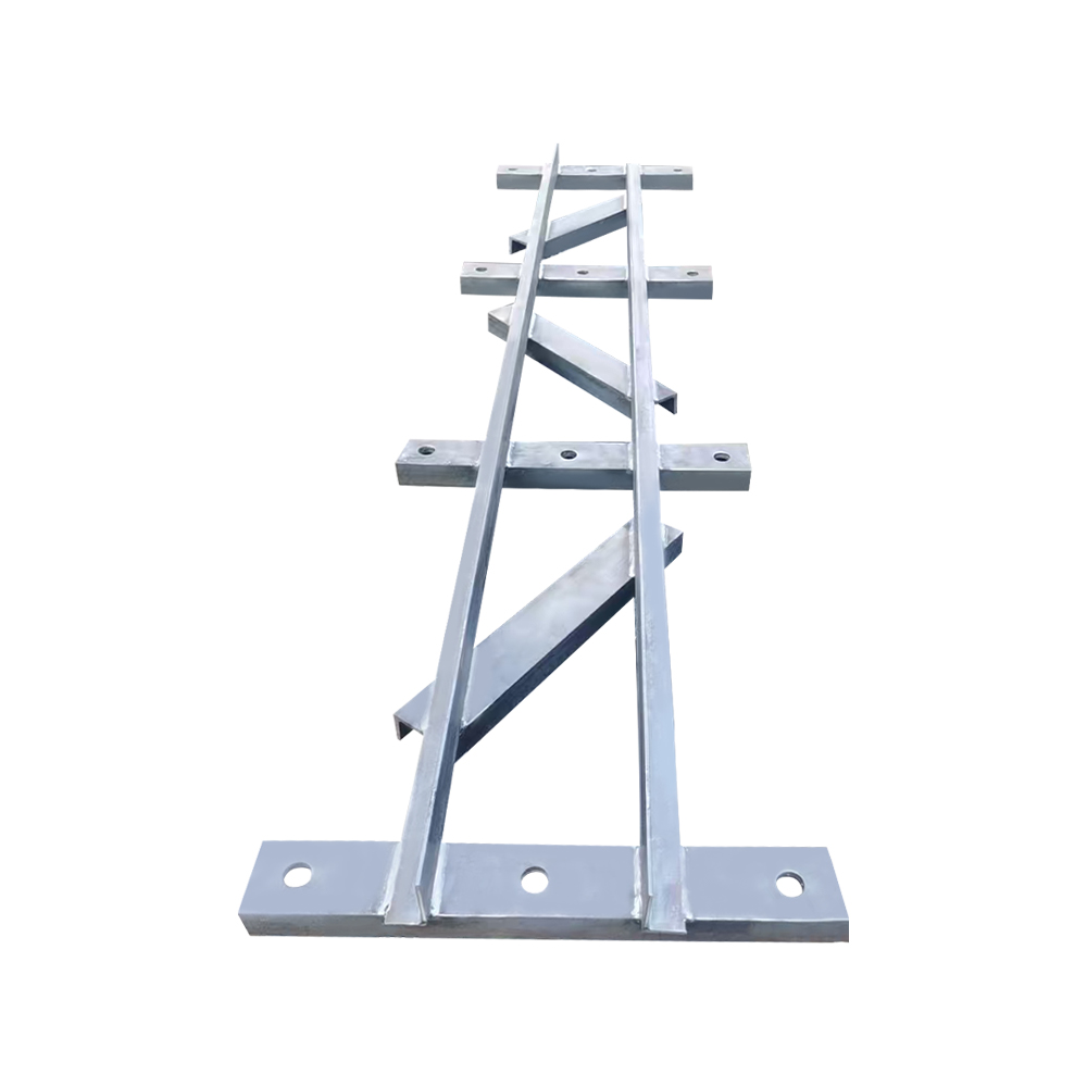
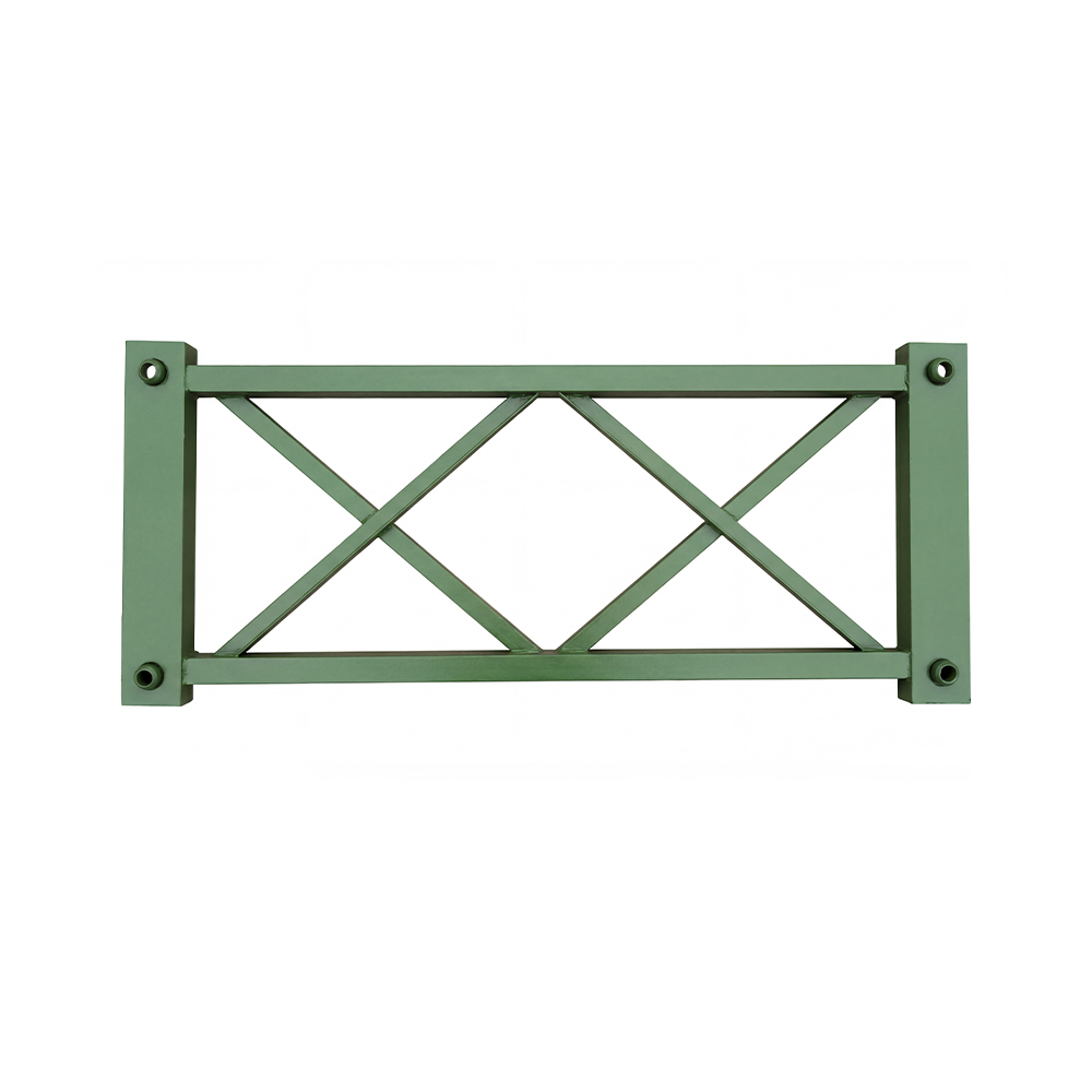
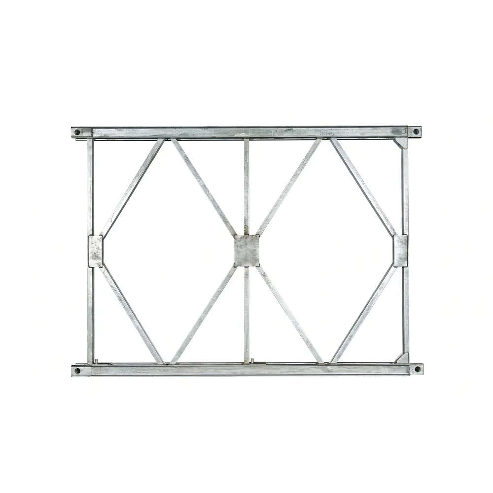
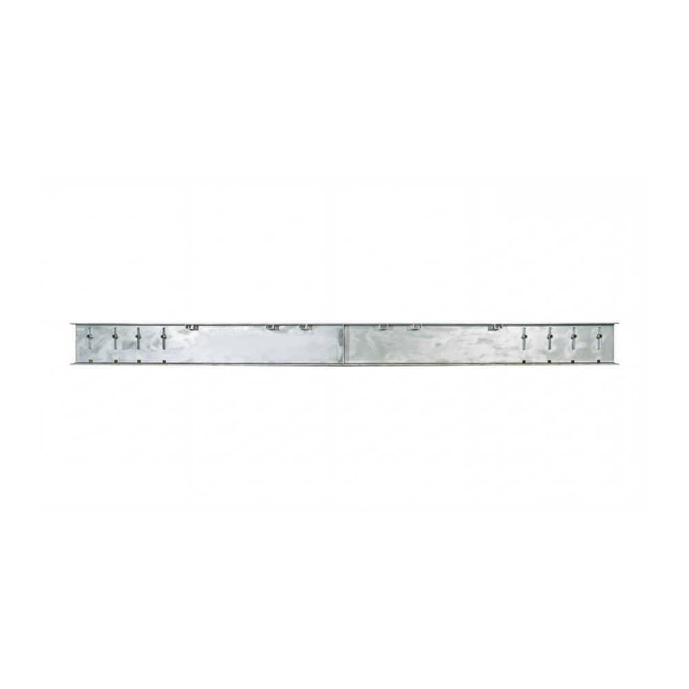
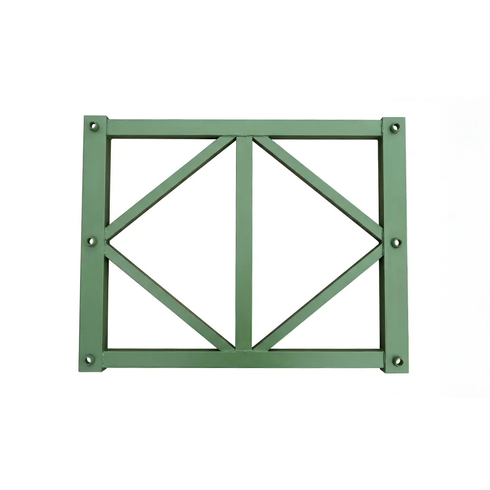
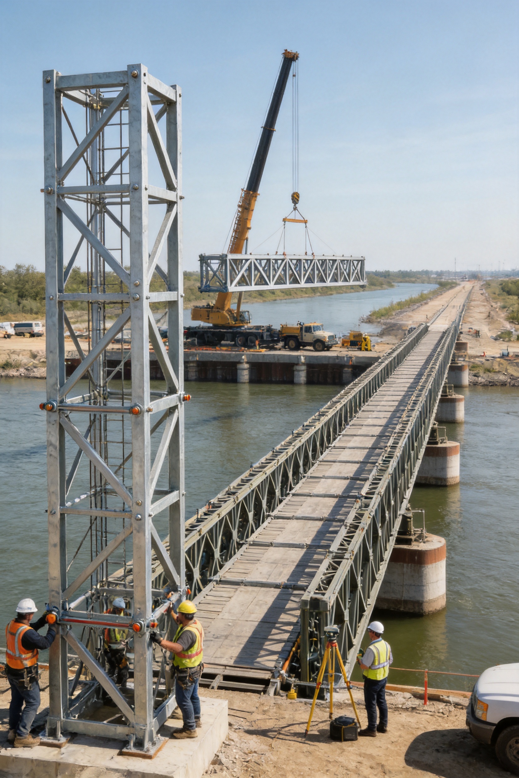
The HD200 Vertical Support Frame is a critical structural component for Type HD200 Bailey bridge systems, heavy-duty prefabricated truss structures, bridge launching arrangements, and large steel formwork support applications. Designed to provide reliable vertical load transfer and improve the stability of assembled trusses, this frame works as part of a complete three-dimensional structural system rather than as an isolated steel member.
In a modular bridge, individual components must connect accurately, carry repeated loads, and remain stable during erection as well as during service. The vertical support frame performs an important role in this process. It helps transfer vertical forces from the upper truss and deck arrangement toward the supporting structure or foundation, while cooperating with horizontal support frames, strengthening chords, and related HD200 components to limit lateral movement, overturning, and excessive deformation.
Available in 730 and 480 specifications, the frame is designed to match the corresponding spacing arrangements of the HD200 truss system. It is manufactured from Q355B structural steel and has a nominal height-related dimension of 1,774 mm, with different widths for the two models. This standardized configuration allows the component to be incorporated into temporary bridges, emergency bridges, semi-permanent bridges, construction support systems, and other engineered steel structures.
The product is manufactured and supplied by Zhenjiang Jinhao Road & Bridge Supporting Engineering Co., Ltd., a Chinese engineering company specializing in Bailey bridges, launching gantry systems, bridge steel formwork, hanging baskets, pier formwork, and related fabricated steel structures. With capabilities covering design, fabrication, erection, leasing, and technical support, the company provides more than individual steel components. It offers coordinated solutions for contractors, infrastructure developers, government projects, and engineering companies.
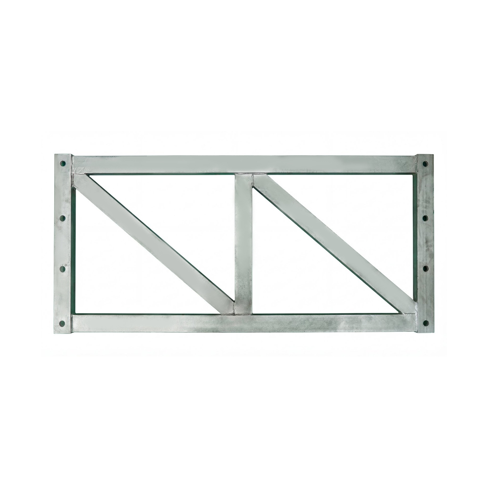
Type HD200 - Vertical Support Frame For Bailey Bridge
1. The Role of a Vertical Support Frame in an HD200 System
A Bailey bridge is assembled from standardized steel components that form a structural load path. Truss panels, transoms, bracing members, deck elements, support frames, and strengthening components must work together to convert applied loads into controlled reactions at the supports. The vertical support frame is one of the components that closes this load path.
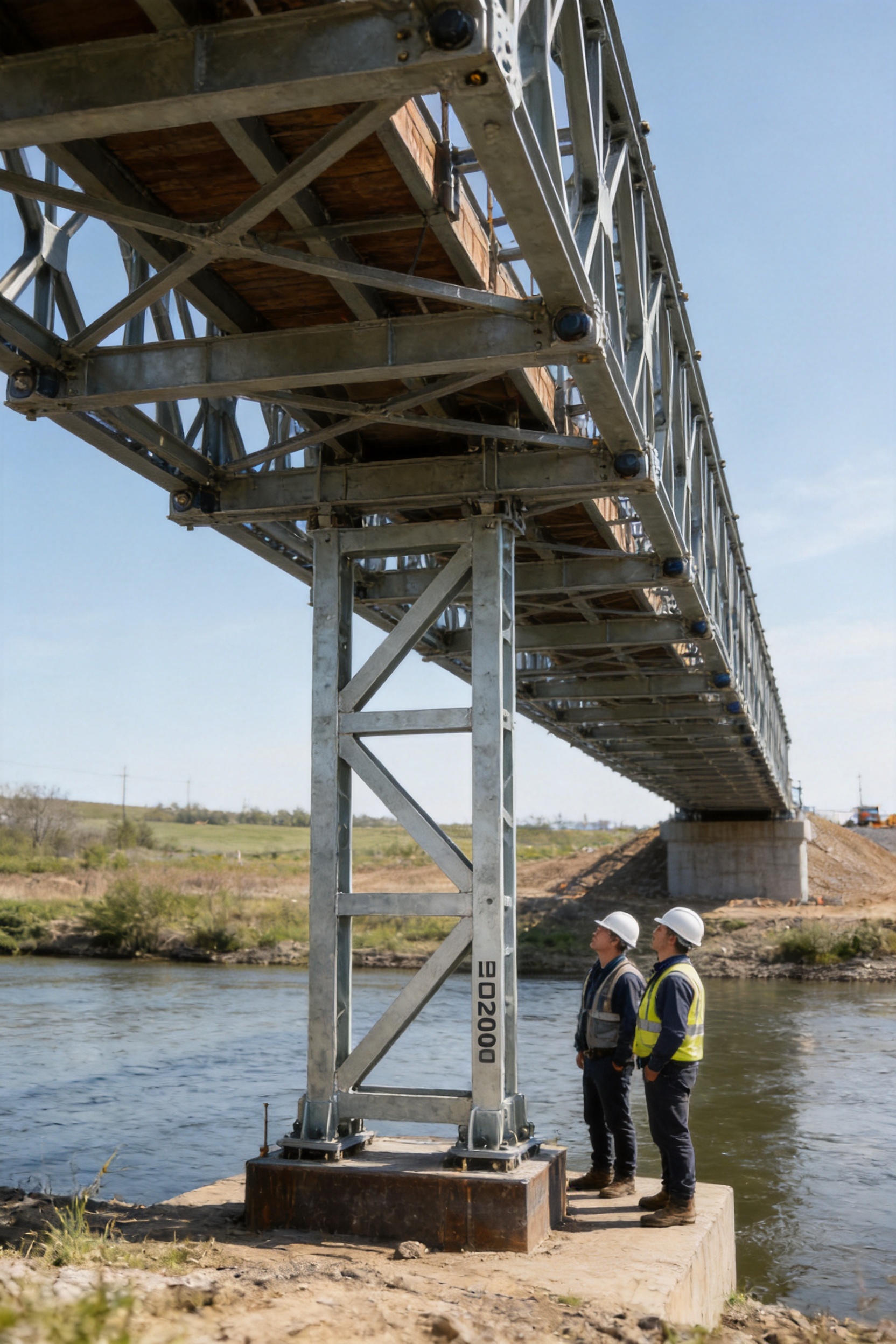
When traffic, equipment, construction materials, or other loads act on the bridge deck, the deck transfers forces to the transoms and trusses. The trusses then distribute these forces along the span and toward the bearings or temporary supports. The vertical support frame helps maintain the relative position of the truss members and transfers vertical reaction forces through the support arrangement. Its function is especially important where the bridge is assembled at a considerable height, carries heavy traffic, or must remain stable during construction operations.
The frame also contributes to geometric control. A modular structure can experience deformation if its members are not adequately restrained or if the support arrangement is poorly configured. By connecting with compatible horizontal support frames and strengthening chords, the HD200 vertical support frame helps maintain the intended structural geometry. This reduces the risk of excessive vertical displacement, unwanted lateral movement, and local instability.
For temporary and emergency bridge projects, installation speed is often as important as ultimate strength. The component must be standardized enough to support rapid assembly but robust enough to withstand demanding site conditions. The HD200 frame is intended for this type of application. Its dimensions correspond to the HD200 system, allowing engineers and erection teams to use a repeatable arrangement rather than fabricate an entirely new support structure for every project.
1.1 Load transfer and stability
The frame is primarily a vertical load-bearing member, but its engineering value extends beyond simple compression resistance. A bridge support arrangement must control several types of behavior, including vertical compression, lateral displacement, local buckling, eccentric loading, and overturning tendencies. The vertical support frame forms part of the restraint system that addresses these behaviors.
In a properly designed assembly, vertical forces are transferred through the connected HD200 members and ultimately into the foundation or supporting substructure. Horizontal frames and strengthening chords help stabilize the arrangement in the transverse and longitudinal directions. The result is a coordinated structural system in which the forces are not concentrated unnecessarily in a single unrestrained member.
The precise capacity of any installation depends on the full structural arrangement, span, support conditions, connection details, wind exposure, traffic loading, erection sequence, foundation capacity, and applicable design standards. Therefore, the vertical support frame should always be selected and installed according to an engineered system design. Its dimensions and material specification provide the basis for integration, but they do not replace project-specific structural verification.
1.2 Importance during bridge erection
Temporary bridges often face their most sensitive stability conditions during erection. Before the deck is fully installed and before all bracing is connected, the partially assembled structure may have limited resistance to lateral forces or torsional movement. Vertical support frames provide an important means of organizing and stabilizing the support arrangement during these intermediate stages.
In bridge launching operations, the structure may be subjected to changing reactions as the leading end moves toward the opposite bank. In such situations, support components must be positioned accurately, connected securely, and checked throughout the launch sequence. A standardized HD200 frame simplifies this process by providing a known geometry that can be incorporated into the erection method statement and temporary works design.
For large formwork support systems, the same principles apply. Concrete formwork, reinforcement, fresh concrete, workers, equipment, and construction vibration can create significant temporary loads. A properly configured vertical support frame can help create a stable steel support tower or supporting arrangement, provided the complete system is designed for the intended load and site conditions.
2. Product Specifications and Configuration
The HD200 Vertical Support Frame is offered in two principal configurations: Model 730 and Model 480. The models correspond to different HD200 truss spacing arrangements. Selecting the correct model is essential because the frame must align with the connected truss members and associated support components.
Item |
Model 730 |
Model 480 |
External dimensions |
1,774 × 820 × 50 mm |
1,774 × 570 × 50 mm |
Center-distance dimensions |
1,694 × (250 + 230 + 250) mm |
Material |
Q355B structural steel |
System compatibility |
HD200 truss spacing |
HD200 truss spacing |
Primary function |
Vertical support, load transfer, and structural stabilization |
The 730 model has an external width of 820 mm, while the 480 model has an external width of 570 mm. Both configurations use the same nominal 1,774 mm dimension and are manufactured from Q355B steel. The difference in width enables the frame to match the applicable HD200 truss spacing without forcing an unsuitable connection arrangement.
The stated center-distance dimensions provide an additional reference for fabrication, checking, and installation. In modular bridge construction, dimensional consistency is essential. Even relatively small deviations can complicate the connection of panels, chords, braces, and transoms. Accurate center distances help ensure that the support frame sits correctly within the overall geometry of the HD200 system.
2.1 Q355B structural steel
Q355B is a commonly used structural steel grade for fabricated load-bearing components. Its mechanical properties provide a suitable balance between strength, weldability, availability, and manufacturability for heavy steel structures. The use of a recognized structural grade also helps engineers and purchasing teams establish a clear material basis for design review and quality documentation.
Material selection should be considered together with fabrication quality. A strong steel grade cannot compensate for poor cutting, inaccurate assembly, defective welds, inadequate surface preparation, or uncontrolled dimensional tolerances. For this reason, the manufacturing process, inspection procedures, and traceability arrangements are as important as the nominal material grade itself.
2.2 Standardized modular geometry
The HD200 system is based on repeatable components. This modular approach provides practical advantages over structures that require extensive site welding or one-off fabrication. Standardized geometry supports faster procurement, simpler transportation planning, easier replacement, and more predictable erection procedures.
For contractors working on several projects, component standardization can also improve inventory management. Compatible frames can be allocated to different bridge configurations, construction support towers, or emergency works, subject to engineering approval. This flexibility is particularly valuable for organizations that maintain reusable temporary works equipment.
3. Engineering Advantages Compared with Conventional Support Arrangements
The HD200 Vertical Support Frame offers several practical advantages when compared with improvised steel supports, non-standard site-fabricated frames, or systems that lack coordinated lateral and longitudinal restraint. These advantages arise from its modular design, defined dimensions, compatible HD200 connections, and role within a complete structural system.
3.1 More predictable structural behavior
A standardized frame provides a known geometry and a defined material specification. This allows engineers to model the support arrangement with greater confidence and to prepare consistent design calculations, shop drawings, erection plans, and inspection checklists. By contrast, improvised supports may contain uncertain member sizes, irregular connection details, or undocumented modifications.
Predictable geometry is particularly important in temporary structures because the design may be reviewed under time pressure. Emergency bridge projects frequently require a rapid response, but speed must not result in unclear structural assumptions. Using a recognized HD200 component can make it easier to establish the basic arrangement before checking project-specific loads and conditions.
3.2 Better compatibility with the HD200 truss system
The two available specifications are intended to correspond with HD200 truss spacing. This compatibility reduces the need for adapters or on-site modifications. When members are designed to work together, connection alignment, bracing layout, and force transfer can be evaluated as a system.
Uncoordinated components can create eccentric connections, uneven bearing, local stress concentrations, or difficult erection sequences. A purpose-designed vertical support frame avoids many of these problems by using a geometry developed for the same modular bridge family.
3.3 Reduced site welding and modification
Site welding can be affected by weather, access, worker qualification, power supply, surface contamination, and inspection limitations. Although field welding is sometimes necessary, reducing unnecessary site fabrication generally improves consistency and saves time. A prefabricated support frame can arrive at the site with its principal fabrication work completed under controlled workshop conditions.
Less site modification also supports better quality control. Workshop production allows the manufacturer to use fixed jigs, dedicated tools, repeatable welding sequences, and systematic dimensional checks. This is especially useful when multiple identical frames are required for a long bridge or a large support structure.
3.4 Improved erection efficiency
Modular frames can be transported, lifted, positioned, and connected according to a planned sequence. Their repeatable dimensions simplify the preparation of lifting plans and temporary support arrangements. Erection crews can become familiar with the connection method and repeat the same operations across multiple locations.
Faster erection can reduce traffic disruption, equipment rental time, labor exposure, and the duration of work over water, railways, roads, or difficult terrain. These benefits are not automatic; they depend on proper planning and safe lifting procedures. However, standardized components provide a stronger foundation for efficient construction than individually fabricated assemblies.
3.5 Reusability and lifecycle value
Bailey bridge components are commonly used in temporary, emergency, and semi-permanent applications. A durable, repairable, and standardized frame can be dismantled after one project and inspected for future use. Reusability can lower the lifecycle cost of temporary works and reduce material waste compared with single-use site-built structures.
Before reuse, each frame should be inspected for deformation, cracks, corrosion, damaged connection areas, unauthorized drilling, and weld defects. Components that no longer meet the required condition should be repaired or removed from service according to a qualified engineering assessment.
4. Manufacturing Strengths and Quality-Control Approach
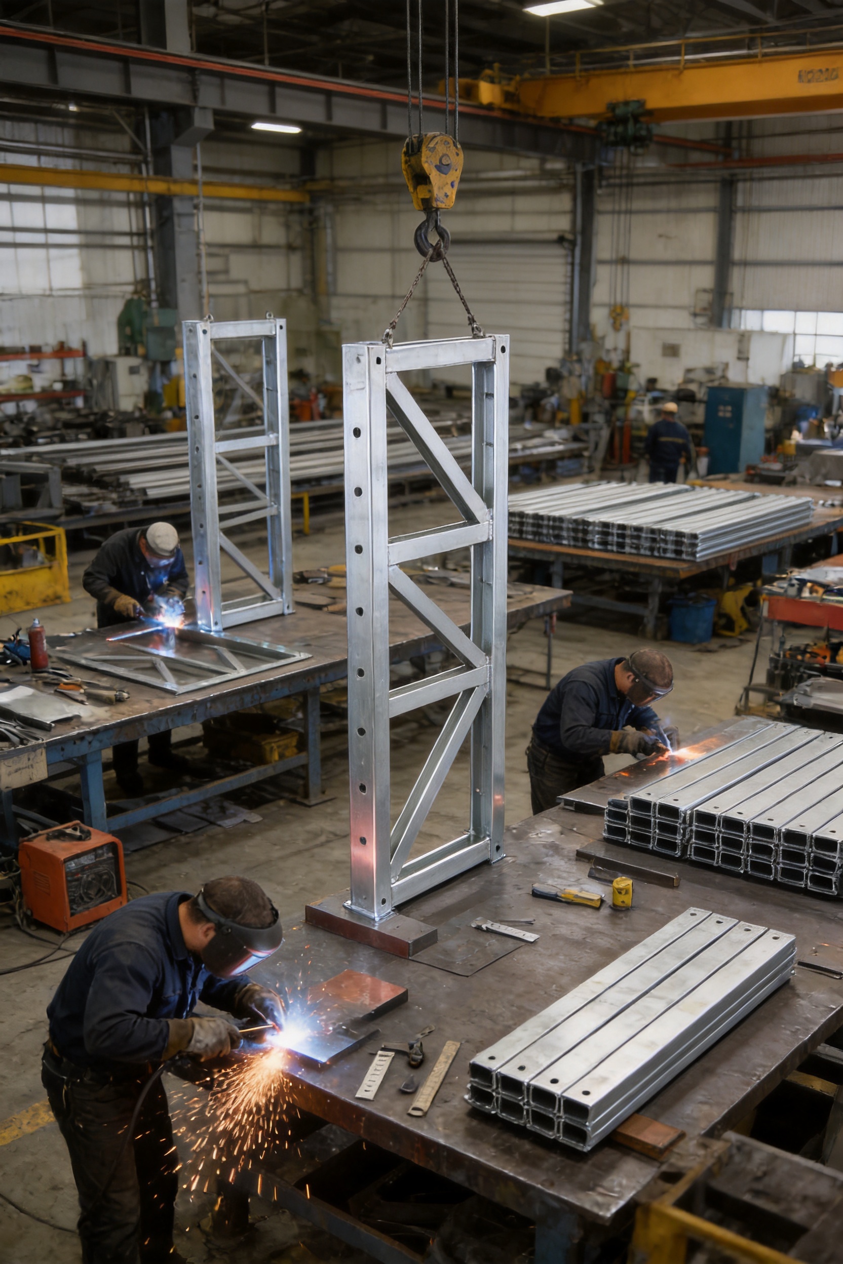
The performance of a structural frame depends heavily on how it is manufactured. Zhenjiang Jinhao Road & Bridge Supporting Engineering Co., Ltd. has developed its business around the design, production, erection, and leasing of steel bridge and construction support products. This integrated experience supports a practical understanding of how components behave not only in the workshop but also during transportation, assembly, launching, and service.
4.1 Engineering-oriented production
An engineering-oriented manufacturer begins with more than a material list. Production must consider the intended structural function, connection sequence, lifting points, transport limitations, installation tolerances, and relationship with neighboring components. For an HD200 vertical support frame, this means maintaining the required external dimensions, center distances, connection positions, and member alignment.
Fabrication drawings should identify material grades, plate thicknesses, weld sizes, connection details, dimensional tolerances, and inspection requirements. Where a project has special requirements, the manufacturer can coordinate with the customer or design consultant to confirm the applicable configuration before production.
4.2 Material control
Q355B steel should be procured from qualified sources and checked against the purchase specification. Material certificates, heat numbers, thickness measurements, and visual condition checks are useful parts of a traceability system. Proper material control helps prevent the substitution of unsuitable steel and provides documentation for project quality records.
Steel plates and sections should be stored in a manner that minimizes contamination, standing water, and mechanical damage. Materials should be identified throughout the production process so that traceability is not lost after cutting or processing.
4.3 Precision cutting and preparation
Accurate cutting is the starting point for dimensional control. Depending on the component design, cutting may be performed using automated flame cutting, plasma cutting, laser cutting, sawing, or other suitable equipment. The selected process should provide clean edges and dimensional accuracy appropriate for the member and connection.
Cut edges may require grinding, removal of slag, correction of sharp irregularities, or preparation for welding. Proper edge preparation supports full and consistent weld fusion. It also helps reduce the possibility of inclusions, incomplete penetration, or irregular weld profiles.
4.4 Assembly using controlled fixtures
Assembly fixtures and positioning jigs are valuable for repeatable production. They hold members in the intended relationship while tack welding and final welding are carried out. For modular components, fixtures can help control the overall width, height, squareness, center distances, and connection alignment.
Controlled assembly is an important advantage over completely manual fabrication. Without suitable fixtures, cumulative dimensional errors can appear as members are added. These errors may not be obvious until the frame reaches the construction site, where correcting them can cause delays and unplanned modifications.
4.5 Welding process control
Welding is a critical part of any fabricated steel support frame. Welding procedures should be selected according to the steel grade, plate thickness, joint configuration, required strength, and applicable standards. Operators should be appropriately trained and qualified for the relevant welding process.
Important controls may include surface cleanliness, preheating where required, consumable storage, welding current and voltage, interpass temperature, welding sequence, and post-weld cleaning. Controlling the welding sequence can also reduce distortion and residual stress, particularly in frames with multiple connected plates and stiffeners.
Visual inspection should be performed on completed welds, with additional non-destructive testing applied where specified by the project design or quality plan. Depending on the joint and risk level, inspection may include magnetic particle testing, ultrasonic testing, dye penetrant testing, or radiographic testing. The exact method should be determined by qualified personnel rather than applied uniformly without regard to the joint type.
4.6 Dimensional inspection
Dimensional inspection confirms that the finished frame corresponds to the approved fabrication drawings. Typical checks include overall height, width, thickness, squareness, straightness, hole or connection positions, center distances, and any required diagonals.
Inspection records should identify the product, model, production batch, measuring equipment, inspection date, and result. For projects requiring formal documentation, these records can be included in the quality dossier together with material certificates, welding records, coating records, and final acceptance documents.
4.7 Surface preparation and protection
Steel support components may be exposed to rain, humidity, mud, salt, construction dust, and chemical contamination. Surface preparation and protective coating can help slow corrosion and preserve the condition of the frame during storage and service.
The coating system should be selected according to the intended environment and project requirements. Surface preparation may include mechanical cleaning or abrasive blasting, followed by primer and finishing coats as specified. Coating thickness, curing conditions, adhesion, and coverage should be checked according to the applicable quality plan.
For components used in harsh environments, the customer should provide information about exposure conditions, expected service duration, immersion risk, and maintenance arrangements. These factors influence the appropriate protection system and inspection frequency.
4.8 Final inspection and dispatch preparation
Before dispatch, each frame should be checked for visible damage, incomplete welds, sharp edges, coating defects, incorrect identification, and deformation. Connection areas should remain compatible with the intended HD200 assembly. Components should be marked or labeled so that the 730 and 480 models are not confused during delivery or erection.
Packaging and loading should prevent impact damage and uncontrolled movement. Where several frames are shipped together, separators or suitable restraints can protect coated surfaces and connection areas. Transport planning should consider the frame dimensions, lifting equipment, route restrictions, and unloading conditions at the project site.
5. Applications of the HD200 Vertical Support Frame
5.1 Temporary and emergency bridges
Temporary bridges provide access during road construction, flood response, disaster recovery, utility works, mining operations, and remote-area development. Emergency conditions often require a solution that can be transported quickly and assembled with commonly available equipment.
The HD200 vertical support frame contributes to the modular nature of the bridge system. It can be used in a planned support arrangement for temporary traffic, logistics vehicles, construction equipment, or emergency access, subject to the approved design load and local regulations.
In flood or disaster response, site conditions may change rapidly. Foundations may be weakened, access may be limited, and installation areas may be uneven. The support frame itself cannot correct inadequate foundations, so ground investigation and bearing verification remain essential. Nevertheless, a standardized component can simplify the structural portion of the response and enable engineers to focus on the specific site constraints.
5.2 Semi-permanent bridge structures
Some projects require a bridge to remain in service for months or years before a permanent structure is completed. A semi-permanent Bailey bridge must be designed with appropriate corrosion protection, inspection access, traffic control, fatigue considerations, and maintenance planning.
The HD200 frame can form part of such a system where its configuration and calculated capacity are suitable. The final design should address not only static vertical loads but also repeated traffic, braking forces, wind, thermal effects, settlement, water flow, and potential impact. The support frame is one part of the bridge and should be evaluated together with the trusses, deck, bearings, piers, and foundations.
5.3 Large formwork support systems
Bridge construction often requires support towers for pier caps, deck formwork, launching areas, or other temporary works. The HD200 vertical support frame can be incorporated into a large steel formwork support arrangement where the system has been designed for the relevant construction loads.
Fresh concrete creates significant pressure and weight. Additional loads may arise from reinforcement, workers, pumps, vibrators, stored materials, wind, and impact. The support arrangement must therefore be checked for vertical capacity, lateral stability, connection strength, foundation settlement, and erection-stage behavior.
Using bridge-system components in formwork support applications can offer flexibility, but the application should not be treated as automatically interchangeable with a bridge arrangement. A separate temporary works design should verify the support tower geometry, bracing, load distribution, and permissible construction sequence.
5.4 Bridge launching and erection equipment
Bailey components can also be used in guide beams, erection towers, gantry support arrangements, temporary piers, and bridge launching systems. In these applications, the vertical support frame may help organize the tower or support geometry and transfer reactions during movement of the bridge structure.
Launching operations involve changing load positions and temporary reactions. Engineers must assess the most unfavorable stages, including the partially launched bridge, nose reactions, support transitions, wind during launching, and possible local contact conditions. The frame is valuable because its standardized dimensions can be integrated into a repeatable launching arrangement, but the complete operation still requires a project-specific method and risk assessment.
5.5 Industrial and civil engineering structures
Beyond bridges, modular steel support components may be used for temporary access platforms, equipment supports, material handling structures, temporary towers, and special construction arrangements. Such uses require confirmation that the frame is appropriate for the applied forces and connection details.
The ability to use a standardized structural component in multiple engineered applications can improve equipment utilization. Contractors may use the same inventory across bridge, formwork, and temporary works projects, provided every application is supported by a suitable design review.
6. Design Considerations for Safe and Effective Use
6.1 Span and loading conditions
The HD200 system is intended for demanding bridge applications, including large-span arrangements broadly described within the 9.144 to 60.96 m range and high-load applications such as HS25 class and above. These figures describe the type of engineering scenario associated with the product family, not a universal capacity for every possible arrangement.
Actual capacity depends on the number of truss lines, panel configuration, strengthening arrangement, span, deck system, support spacing, lateral bracing, load class, impact factor, wind, and foundation conditions. Engineers should calculate the complete bridge system using the applicable national or international design standard.
6.2 Foundation and bearing capacity
A strong superstructure cannot perform reliably on an inadequate foundation. Concentrated reactions from a temporary bridge or support tower may exceed the allowable bearing capacity of soil, fill, pavement, or an existing structure. Foundation investigation should consider soil type, groundwater, settlement, scour, erosion, and construction-stage loading.
Where the natural ground is weak, the support arrangement may require spreader beams, grillages, piles, concrete footings, steel stools, or other engineered measures. The vertical support frame helps transfer forces, but it does not eliminate the need for adequate bearing area and foundation stability.
6.3 Lateral bracing
Vertical frames should not be installed without the required horizontal frames and strengthening chords. A support arrangement with insufficient bracing may have adequate theoretical vertical compression resistance but poor resistance to lateral movement or overturning.
Bracing should be installed according to the approved drawings and erection sequence. Members should not be omitted merely because the structure appears stable at a particular stage. Temporary structures can be vulnerable to wind, equipment contact, uneven loading, and accidental impact before the final configuration is complete.
6.4 Connection inspection
Connections are essential to force transfer. Before loading, bolts, pins, washers, locking devices, welds, bearing surfaces, and connecting plates should be checked. Damaged or distorted connection components should not be forced into place or modified without engineering approval.
Bolted connections should be tightened according to the specified procedure. Pin connections should be fully seated and secured. Any required anti-loosening devices should be installed. Inspection should continue after initial loading because settlement or vibration may reveal problems that were not visible during erection.
6.5 Erection sequence
The sequence of assembly affects the forces in the structure. A procedure that is safe after completion may not be safe during partial assembly. The erection plan should define the order of frame installation, bracing, lifting, launching, deck placement, temporary supports, and removal of construction aids.
Personnel should be protected from falling objects, suspended loads, unprotected edges, water hazards, traffic, and moving equipment. The use of cranes, winches, jacks, launching noses, or other equipment should be governed by a site-specific lifting and safety plan.
6.6 Inspection during service
Temporary does not mean maintenance-free. The bridge or support system should be inspected at regular intervals and after unusual events such as flooding, collision, excessive vibration, fire, strong wind, or unexpected settlement.
Inspection should look for corrosion, bent members, cracked welds, loose bolts, damaged pins, coating failure, deck deterioration, abnormal deflection, foundation movement, and changes in alignment. A record of inspections helps identify progressive deterioration and supports responsible decisions about repair, continued use, load restriction, or dismantling.
7. Why an Integrated Manufacturer Matters
Purchasing a structural component from a company with experience in related bridge systems can reduce coordination difficulties. Zhenjiang Jinhao Road & Bridge Supporting Engineering Co., Ltd. works across several product categories, including Type 321 Bailey truss sections, HD200 or Type 200 Bailey truss sections, bridge launching gantries, triangular and diamond hanging baskets, bridge steel formwork, pier formwork, and other engineered steel products.
This product range gives the company practical exposure to the interfaces between individual components. A vertical support frame does not operate independently. It must relate to truss sections, horizontal frames, strengthening chords, deck systems, temporary piers, launching equipment, and foundation arrangements. An integrated supplier is better positioned to discuss these interfaces than a manufacturer that produces only generic steel plates or isolated fabricated members.
7.1 Design and system planning
Project requirements vary widely. A contractor may need a short emergency crossing, a heavy-duty temporary highway bridge, a support tower for formwork, or a launching arrangement for a permanent bridge. Each application requires different calculations, accessories, connection details, and erection methods.
System planning helps identify the required component quantity, configuration, transport sequence, lifting equipment, support spacing, and site resources. It also helps prevent the common problem of ordering the principal truss members while overlooking support frames, bracing, deck components, bearings, connection hardware, or erection tools.
7.2 Customized fabrication
Although modular systems rely on standard components, projects may require customized accessories, special support arrangements, modified deck widths, non-standard end conditions, or additional steelwork. A manufacturer with fabrication experience can evaluate whether a requirement can be achieved through a standard configuration, an approved accessory, or a specially engineered component.
Customization should be controlled through drawings, technical reviews, and documented approval. Uncontrolled field alterations can reduce the reliability of a standardized structural system. Properly managed customization, by contrast, can extend the usefulness of the system while preserving engineering discipline.
7.3 Erection and technical support
Technical support is valuable when a project involves difficult access, restricted construction windows, water crossings, railway interfaces, high traffic volumes, or complicated launching conditions. Advice on assembly sequence, component identification, lifting, temporary stability, and inspection can help the contractor coordinate the work more effectively.
Where required, the company can support erection-related activities in addition to manufacturing. This combination of product knowledge and field experience can help identify practical problems before they become delays at the construction site.
7.4 Leasing and reusable equipment
Temporary bridge components do not always need to be purchased outright. Leasing can be attractive for short-duration works, emergency response, seasonal access, or contractors that do not want to maintain a large inventory. A supplier involved in both manufacturing and leasing may be able to provide equipment matched to a project duration and configuration.
Leased components should still be subject to inspection, documentation, and acceptance procedures. The customer should confirm the condition of the equipment on arrival and establish responsibilities for installation, maintenance, repair, and return.
8. Procurement and Project Coordination
Before ordering an HD200 Vertical Support Frame, the purchaser should provide enough project information for the correct model and quantity to be selected. Useful information includes the bridge type, span, roadway width, design load, number of truss lines, deck arrangement, support spacing, erection method, environmental exposure, and anticipated service duration.
The customer should also clarify whether the requirement is for the frame only or for a complete HD200 bridge package. A complete package may include truss panels, vertical and horizontal support frames, strengthening chords, transoms, bracing, deck units, bearings, bolts, pins, walkways, ramps, launching equipment, and other accessories.
Procurement stage |
Recommended action |
Initial inquiry |
Provide span, load, width, application, site conditions, and required delivery schedule. |
Technical review |
Confirm whether Model 730 or Model 480 matches the proposed HD200 configuration. |
Engineering coordination |
Review support spacing, bracing, foundation reactions, connections, and erection sequence. |
Manufacturing |
Confirm material, drawings, welding, dimensional inspection, coating, and identification requirements. |
Pre-shipment inspection |
Check quantity, model, dimensions, condition, documentation, and packaging. |
Site acceptance |
Inspect for transport damage and verify compatibility before installation. |
Installation |
Follow the approved erection plan and complete connection and stability checks. |
Operation and maintenance |
Inspect regularly and record any deformation, corrosion, settlement, or connection problems. |
Delivery schedules should account for drawing approval, material procurement, fabrication, inspection, coating, packing, shipping, customs, and site readiness. If the bridge is required for emergency access, early technical coordination is especially important because transport and foundation preparation can take as long as fabrication.
9. Installation Workflow
A typical installation begins with site preparation. The construction team establishes the bridge centerline, support locations, working platforms, access routes, lifting areas, and foundation levels. Survey controls should be set before the first support frame is positioned.
Next, the support bases or temporary piers are prepared. Their elevation and alignment should be checked against the approved design. Any packing plates, grillages, bearings, stools, or leveling arrangements should be installed as specified.
The vertical support frames are then positioned in the correct orientation and connected to the associated horizontal support frames or other members. The erection team should verify model identification because Model 730 and Model 480 have different external widths.
Strengthening chords and bracing members are installed as the support arrangement rises or as the bridge assembly progresses. Temporary stability must be maintained at every stage. The structure should not be left partially assembled in a configuration that has not been reviewed by the temporary works designer.
After the main support arrangement is complete, the truss sections, transoms, deck elements, and other bridge components are installed according to the method statement. Connections are inspected progressively rather than waiting until the entire bridge has been assembled.
Before opening the bridge or applying construction loads, the responsible engineer should review the completed structure. The review may include survey measurements, bolt and pin checks, visual inspection, deck checks, bearing checks, foundation observations, and a controlled proof or commissioning procedure where required.
10. Maintenance, Inspection, and Reuse
Regular inspection protects both safety and lifecycle value. The first inspection should be completed after erection and initial loading. Further inspections should follow the project maintenance plan, with additional checks after severe weather, impact, flooding, abnormal vibration, or observed settlement.
Steel surfaces should be checked for corrosion, especially near connections, drainage points, contact surfaces, and areas where mud or water can accumulate. Damaged coating should be cleaned and repaired using a compatible system. Corrosion that has reduced the member thickness or affected a connection should be assessed by a qualified engineer.
Welded areas should be examined for visible cracks, undercut, porosity, deformation, or other signs of distress. Bolts, pins, and locking devices should be checked for looseness, wear, elongation, or damage. Any unusual movement or noise during service should be investigated promptly.
When the frame is dismantled for reuse, it should be cleaned, catalogued, and inspected. Components should be separated according to model and condition. Frames that have suffered serious deformation, fire exposure, impact, or unauthorized modification should not be returned to service without formal assessment.
11. Environmental and Operational Benefits
Modular steel bridge systems can reduce the time required to establish access over obstacles. Shorter construction periods may reduce traffic disruption, land occupation, equipment operation, and disturbance to surrounding activities. In emergency works, this can support faster restoration of transport and logistics routes.
Reusable steel components can also offer resource advantages. A vertical support frame that is dismantled and redeployed for several projects may provide more lifecycle value than a temporary structure designed for one use. Steel is also suitable for recycling at the end of its useful life, although responsible handling and material separation are required.
Environmental performance depends on the complete project. Transport distance, coating materials, foundation construction, site access, maintenance, and eventual reuse all influence the total impact. A modular component is therefore one part of a broader sustainability strategy rather than a guarantee of low environmental impact in every situation.
12. Frequently Asked Questions
12.1 What is the primary purpose of the HD200 Vertical Support Frame?
Its primary purpose is to provide vertical load-bearing support within an HD200 Bailey bridge or related heavy-duty truss arrangement. It helps transfer vertical reactions and contributes to resistance against overturning, lateral movement, and excessive deformation when connected with the appropriate horizontal frames and strengthening chords.
12.2 Which models are available?
The product is available in Model 730 and Model 480. Model 730 has external dimensions of 1,774 × 820 × 50 mm, while Model 480 has external dimensions of 1,774 × 570 × 50 mm. The correct model depends on the spacing arrangement of the HD200 truss system.
12.3 What material is used?
The frame is manufactured from Q355B structural steel. The material provides a recognized basis for structural fabrication, but the final performance also depends on fabrication quality, welding, dimensional accuracy, connections, corrosion protection, and the complete structural design.
12.4 Can the frame be used by itself?
No. The frame is a component of an engineered system. It should be used with compatible HD200 truss sections, horizontal support frames, strengthening chords, bracing, connection hardware, and foundations as required by the design. Installing it without adequate system restraint can create instability.
12.5 Is it suitable for emergency bridges?
It is suitable for inclusion in emergency and temporary bridge systems where the HD200 configuration is appropriate. The project must still verify span, design loading, site conditions, foundation bearing capacity, wind, water effects, traffic requirements, and erection safety.
12.6 Can it be used for bridge formwork support?
It can be incorporated into large formwork support systems when specifically designed for that application. Formwork loads include fresh concrete, reinforcement, workers, equipment, vibration, and wind. A separate temporary works design should confirm the support arrangement and construction sequence.
12.7 What is the advantage of using a standardized frame instead of site-fabricated steel?
A standardized frame offers more predictable dimensions, repeatable connections, easier inspection, reduced site welding, faster assembly, and improved potential for reuse. It also allows engineers to work with a known modular component rather than an improvised structure with uncertain geometry.
12.8 Does the manufacturer provide more than the frame?
Yes. Zhenjiang Jinhao Road & Bridge Supporting Engineering Co., Ltd. provides Bailey bridge components, Type 321 and HD200 truss sections, launching gantries, hanging baskets, bridge steel formwork, pier formwork, customized fabricated steel structures, erection support, design coordination, and leasing services.
12.9 What information should be provided for a quotation?
The purchaser should provide the intended application, bridge span, roadway width, design load, truss arrangement, support spacing, number of frames, site conditions, delivery location, required accessories, and schedule. Drawings or preliminary layouts are helpful for confirming the correct model and complete bill of materials.
12.10 How should the frame be maintained?
Inspect it for corrosion, cracks, deformation, coating damage, loose connections, and abnormal movement. Inspections should be conducted after erection, during service, after severe events, and before reuse. Any serious damage or modification should be assessed by a qualified engineer before the frame is loaded again.
12.11 Is the product suitable for permanent bridges?
The frame is primarily associated with temporary, emergency, semi-permanent, and modular heavy-duty applications. It may be used in a longer-duration structure only when the complete design, material protection, fatigue performance, inspection plan, and regulatory requirements have been properly addressed.
12.12 Does the stated span range define the capacity of every bridge?
No. The stated 9.144 to 60.96 m range describes large-span engineering scenarios associated with the product application. Actual capacity must be calculated for the specific span, loading, truss arrangement, deck, bracing, support conditions, foundation, and environmental effects.
13. Selecting a Reliable Supply Partner
A reliable supplier should be able to demonstrate clear product identification, material information, fabrication capability, dimensional control, welding quality, inspection procedures, packaging discipline, and technical communication. For modular bridge systems, the supplier should also understand how individual parts interact within the completed structure.
Zhenjiang Jinhao Road & Bridge Supporting Engineering Co., Ltd. was established in 2017 and is located in Zhenjiang, Jiangsu Province, China. Its business has developed from construction and industrial material marketing into an integrated enterprise involved in the design, manufacture, erection, and leasing of Bailey bridges, launching gantries, hanging baskets, bridge formwork, pier formwork, and related steel products.
The company serves contractors, government organizations, infrastructure developers, and engineering companies in domestic and international markets. Its product range and project-oriented services support applications in transportation engineering, municipal works, water conservancy, railway construction, national defense readiness, emergency response, and general civil engineering.
For customers purchasing an HD200 vertical support frame, this broader capability can be useful because the frame may need to be coordinated with other bridge components or incorporated into a special temporary works arrangement. The ability to discuss fabrication, system planning, erection, and leasing in one supply relationship can reduce communication gaps and support more efficient project execution.
14. Conclusion
The HD200 Vertical Support Frame is a purpose-designed component for creating stable and efficient support arrangements within HD200 Bailey bridge systems and heavy-duty modular steel structures. Its two configurations, Model 730 and Model 480, provide compatibility with different HD200 truss spacing requirements. Manufactured from Q355B steel and based on standardized dimensions, the frame supports repeatable fabrication, transportation, inspection, erection, and reuse.
Its main engineering value lies in its role within a complete structural system. By working with horizontal support frames, strengthening chords, truss sections, bracing, deck components, and foundations, it contributes to vertical load transfer, geometric control, and resistance to instability. These features make it suitable for temporary bridges, emergency access structures, semi-permanent crossings, large formwork support systems, launching arrangements, and other engineered steel applications.
Compared with improvised site-fabricated supports, a standardized HD200 frame can provide more predictable geometry, better component compatibility, reduced site welding, faster assembly, easier inspection, and greater potential for reuse. Its benefits are strengthened when supplied by an experienced manufacturer with capabilities in design coordination, controlled fabrication, steel bridge production, erection support, technical service, and equipment leasing.
Successful use still depends on proper engineering. Span, load, foundation, bracing, connections, erection sequence, wind, water, traffic, corrosion, and inspection requirements must all be addressed. When these factors are managed through a qualified design and construction plan, the HD200 Vertical Support Frame can provide a practical and dependable element in modern modular bridge and temporary works construction.
References
1. Product technical information for the HD200 Vertical Support Frame, including Model 730 and Model 480 dimensions and Q355B material specification.
2. Modular Bailey bridge design and erection principles for temporary, emergency, and semi-permanent steel bridges.
3. Structural steel fabrication practices covering material traceability, cutting, assembly, welding, dimensional inspection, and protective coating.
4. Temporary works engineering principles for bridge launching, formwork support, temporary towers, and construction-stage stability.
5. General guidance on inspection, maintenance, corrosion protection, and reuse of prefabricated steel bridge components.
6. Project-specific national standards and engineering specifications applicable to bridge loading, structural steelwork, foundations, welding, lifting, and temporary structures.


 Français
 Español
 عربى