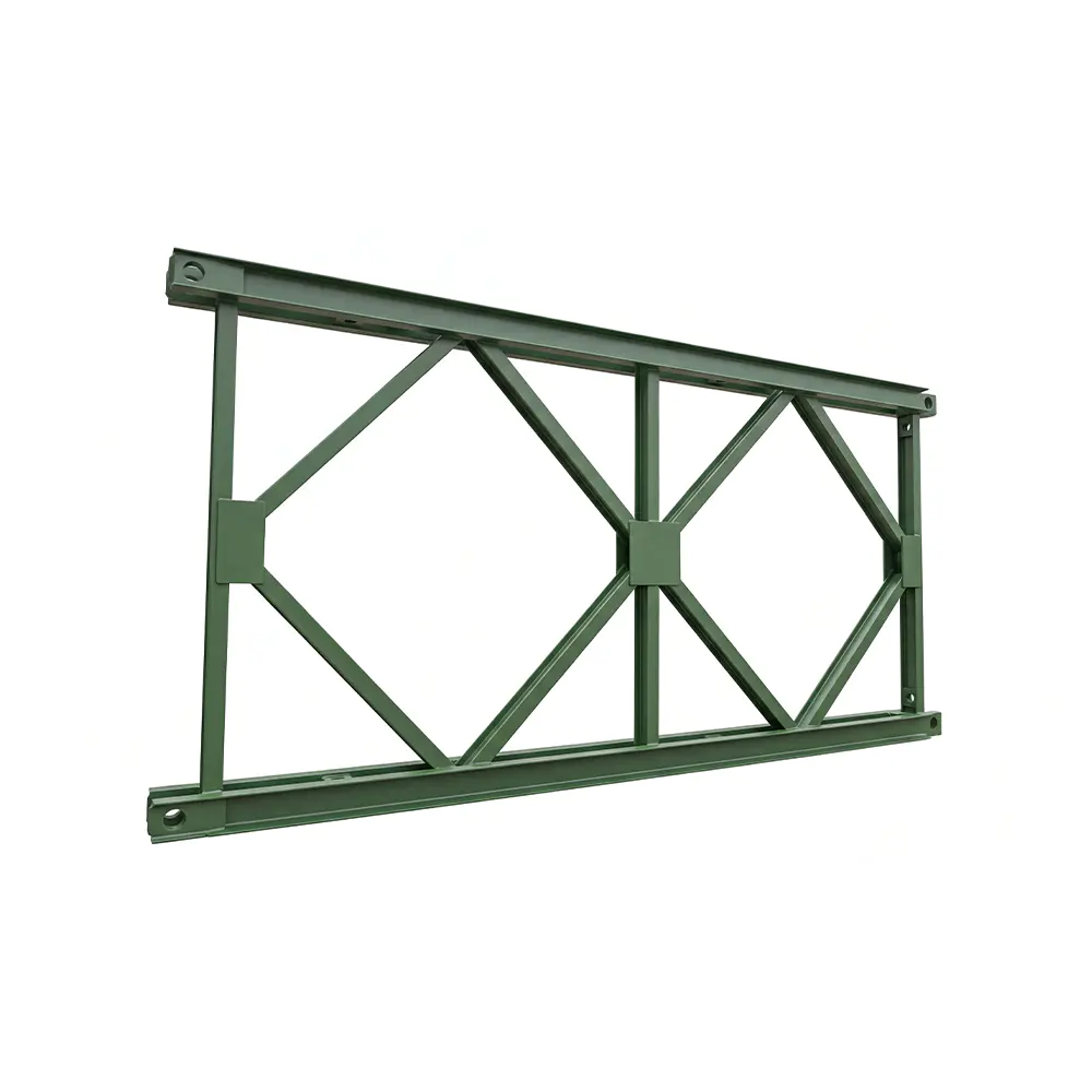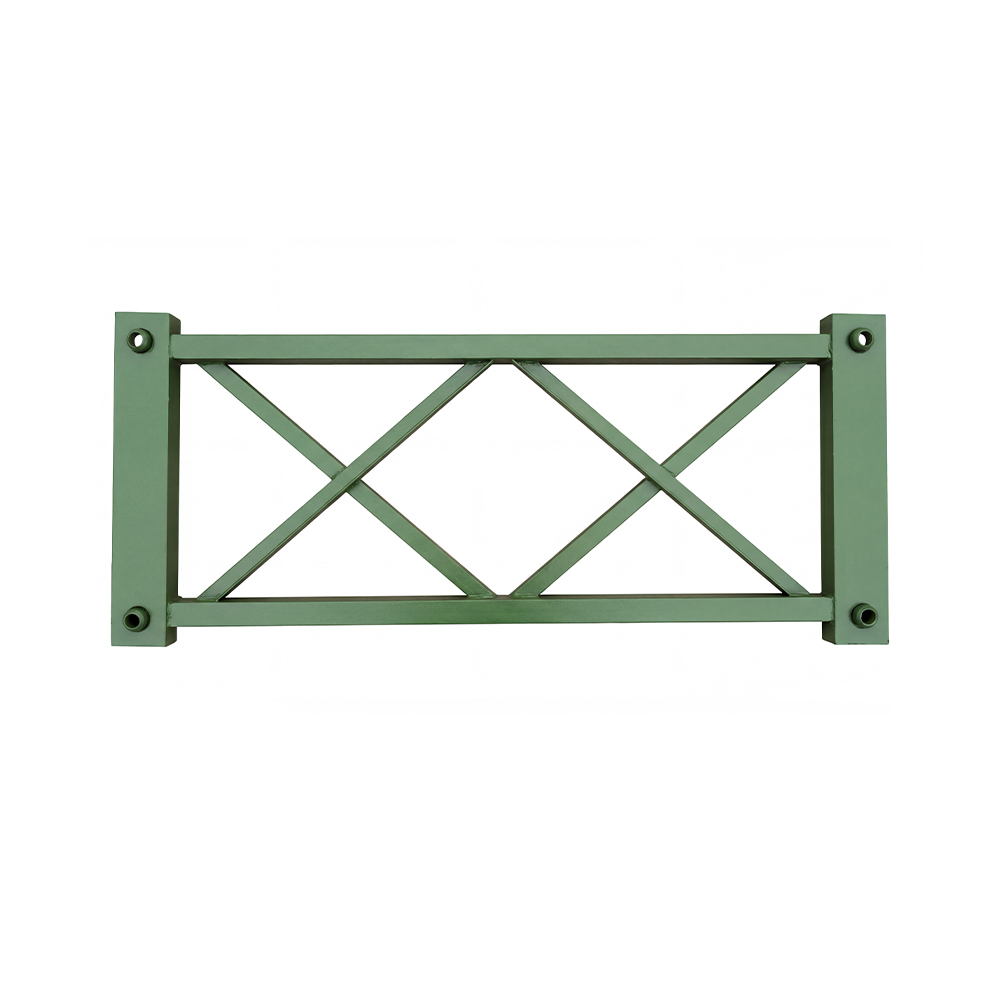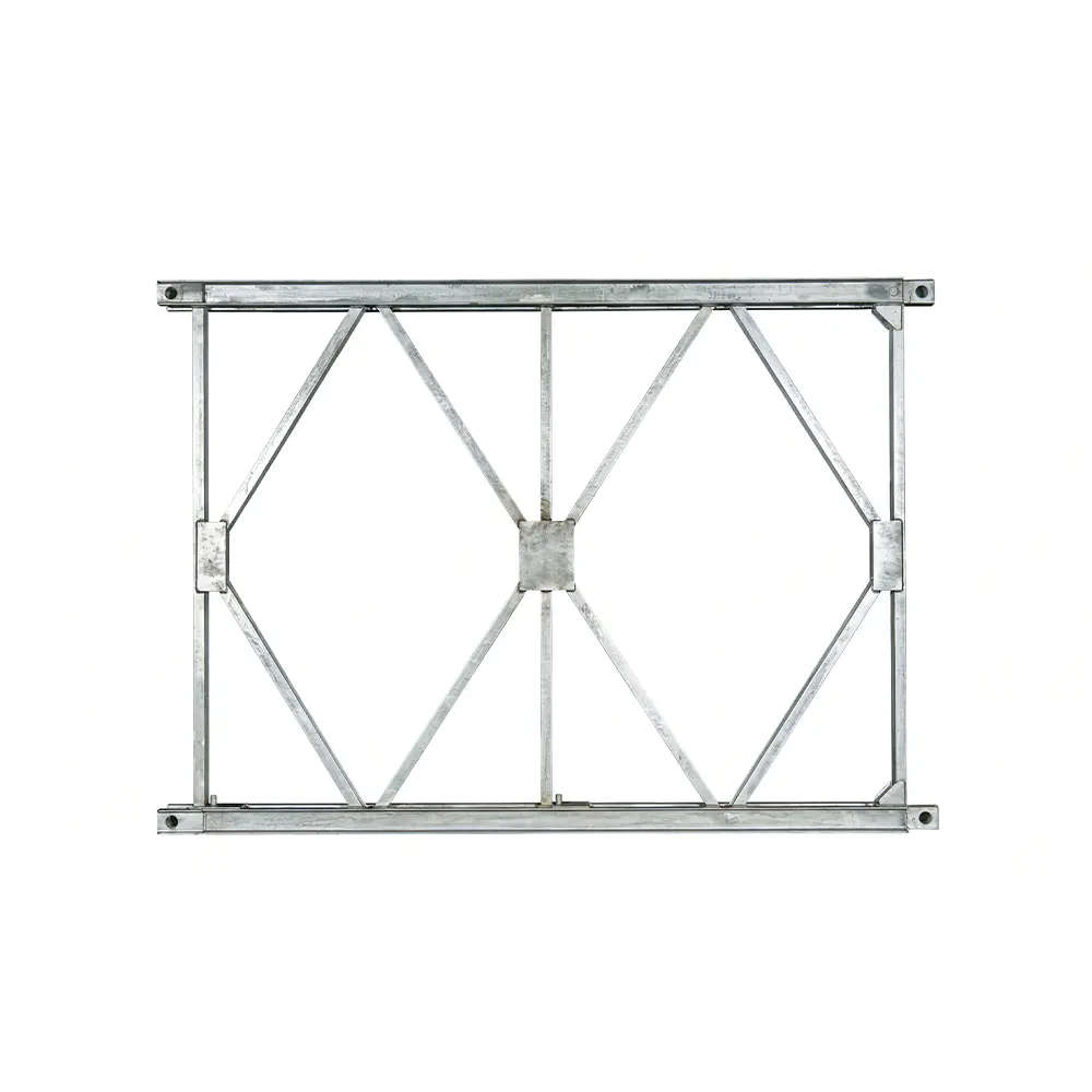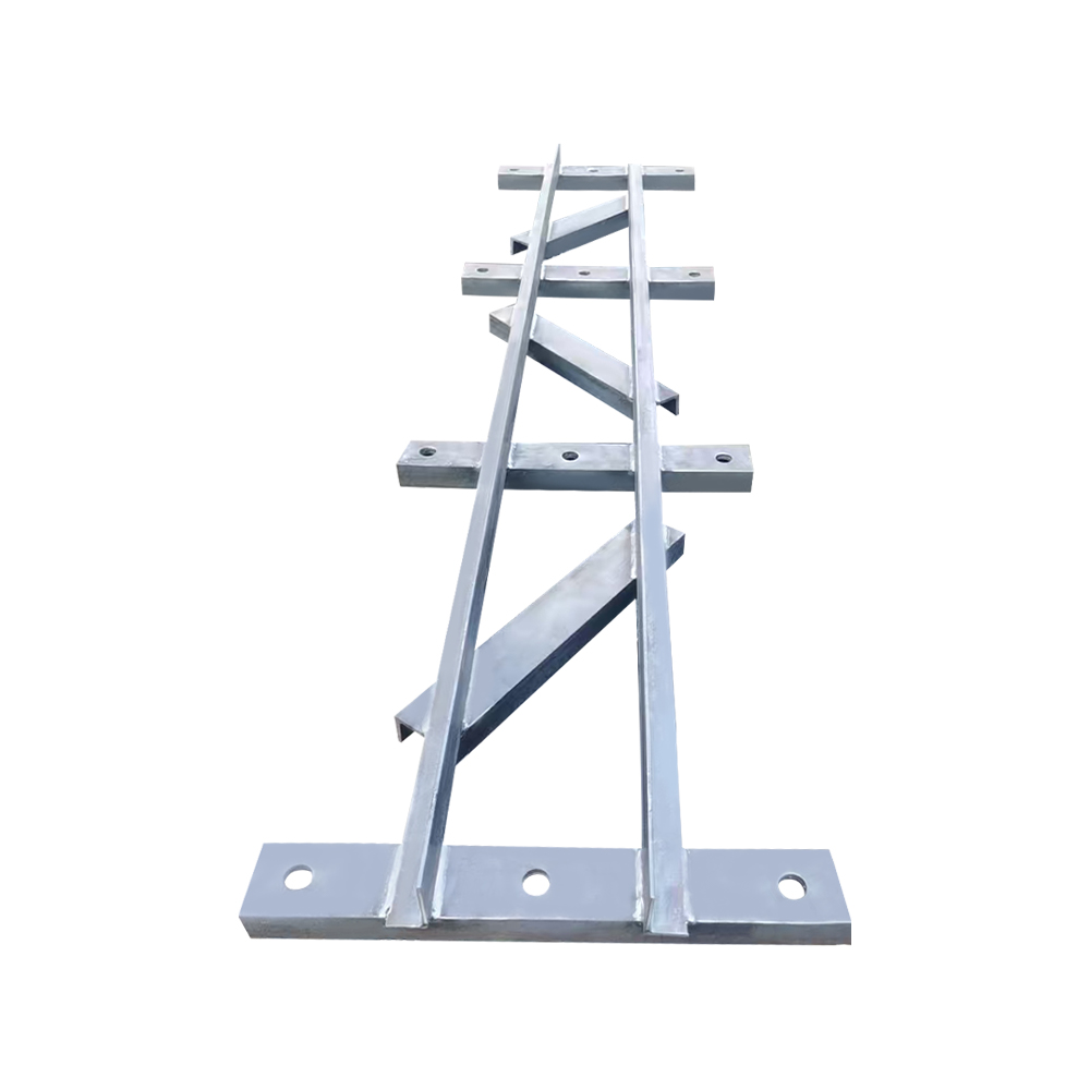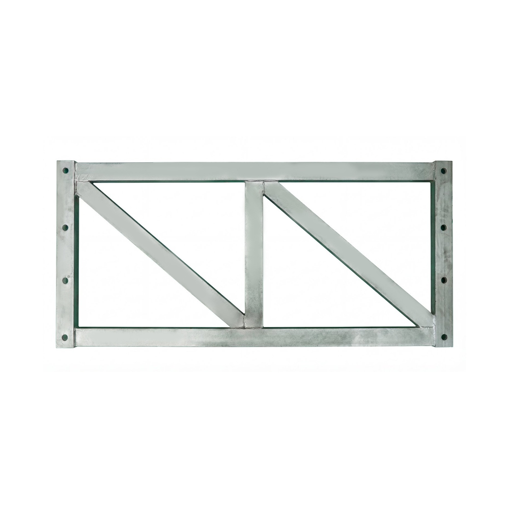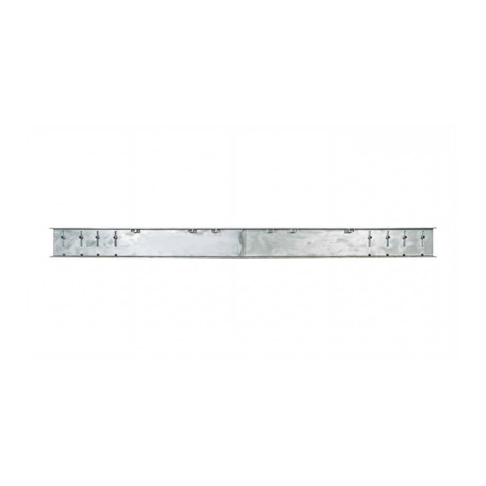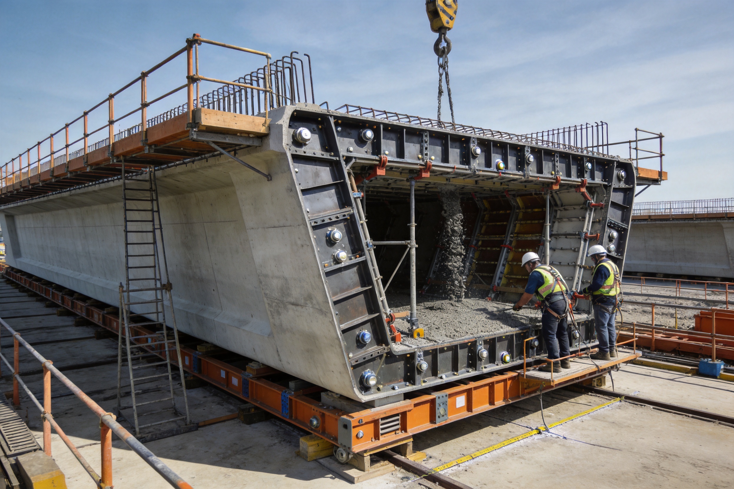
Box girder formwork is a specialized steel forming system used to shape the complex cross-section of prestressed and reinforced concrete box girders. It creates the external surfaces, internal voids, webs, flanges, and bottom slabs that together form a strong, lightweight, and highly efficient bridge beam. Compared with conventional flat-panel formwork, a properly engineered box girder system provides greater dimensional stability, improved resistance to concrete pressure, more reliable sealing, and better adaptability to demanding bridge construction methods.
Box girder bridges are widely used in highway, railway, urban transport, viaduct, and large-span infrastructure projects. Their closed or partially closed cross-sections offer an excellent balance between structural weight, bending resistance, torsional stiffness, and usable deck width. However, these same geometric advantages create more complicated construction requirements. The formwork must accurately reproduce multiple surfaces at the same time while maintaining alignment, resisting fresh concrete pressure, allowing reinforcement and prestressing work, and supporting efficient stripping and relocation.
For this reason, box girder formwork is not simply a collection of steel plates. It is an integrated engineered system consisting of panels, stiffeners, support frames, connection components, adjustment mechanisms, access provisions, sealing details, and lifting or handling arrangements. The quality of every element influences the final beam. Poorly aligned panels can produce dimensional deviations, while weak joints may result in grout leakage, honeycombing, surface defects, and costly repair work.
Zhenjiang Jinhao Road & Bridge Supporting Engineering Co., Ltd. manufactures bridge steel formwork and related engineered steel structures for contractors, bridge builders, infrastructure companies, and project owners. Its experience in steel bridge products, launching gantry systems, hanging baskets, pier formwork, and other bridge construction equipment supports a coordinated approach to the design and fabrication of box girder formwork.
1. The Role of Box Girder Formwork in Modern Bridge Construction
A box girder is generally composed of a top slab, bottom slab, one or more webs, and internal voids. Depending on the project, the cross-section may be single-cell, twin-cell, or multi-cell. It may also include sloped webs, thickened diaphragms, curved soffits, cantilevered deck slabs, inspection openings, drainage provisions, and prestressing ducts. The formwork must accommodate all these features without compromising stability or construction speed.
During casting, fresh concrete applies considerable lateral and vertical pressure to the formwork. The pressure varies according to concrete fluidity, placement speed, vibration intensity, temperature, and the height of the pour. The formwork must therefore remain stable throughout the entire operation. It must not bulge, twist, separate at joints, or shift from the designed position.
External formwork defines the visible geometry of the girder, while internal formwork creates the hollow core. In many projects, the internal form is particularly challenging because access is restricted and the available space for workers and equipment is limited. A well-designed system uses modular components and practical adjustment mechanisms to simplify assembly, inspection, concrete placement, and stripping.
Box girder formwork can be used in several construction arrangements:
• Cantilever casting for segmental or balanced cantilever bridge construction.
• In-situ casting on scaffolding or temporary support structures.
• Standardized production in a prefabrication or precast yard.
• Repetitive casting of bridge segments with controlled dimensional tolerances.
• Specialized casting for large-span highway and railway bridge structures.
Each method places different demands on the formwork. Cantilever casting requires compactness, accurate adjustment, and compatibility with a traveler or hanging basket. In-situ casting requires strong support and reliable positioning over temporary works. Prefabrication emphasizes repeatability, rapid cycling, handling efficiency, and consistent surface quality.
2. Main Advantages of High-Quality Box Girder Formwork
2.1 Strong Overall Rigidity
One of the most important advantages of steel box girder formwork is its strong overall rigidity. A rigid system maintains the designed shape when subjected to fresh concrete pressure, vibration, construction loads, and repeated use. This is especially important for wide decks, deep girders, large cells, and long casting sections.
High rigidity is achieved through a combination of properly designed steel panels, longitudinal stiffeners, transverse ribs, support frames, adjustable braces, and reliable connection points. These elements work together as a structural system rather than as isolated components. The result is reduced deformation and improved dimensional control across the entire casting surface.
Compared with improvised timber systems or lightly reinforced panels, engineered steel formwork is better suited to repetitive bridge construction. It can maintain its geometry over many casting cycles when correctly handled and maintained. This reduces the risk of progressive distortion, which can become more serious as a project advances.
2.2 Excellent Resistance to Lateral Pressure
Fresh concrete exerts lateral pressure on webs, side panels, and internal form surfaces. The pressure is affected by concrete slump, placement sequence, pouring speed, temperature, and vibration. A formwork system with insufficient strength may deform outward or develop leakage at its joints.
Box girder formwork is designed with load-bearing members that distribute pressure across the panels and into the supporting structure. Properly arranged stiffeners prevent local plate buckling and reduce stress concentration around connections. The formwork can therefore withstand demanding concreting conditions while preserving the required beam profile.
Resistance to lateral pressure is also valuable when using high-performance or self-consolidating concrete. These mixtures may remain fluid for longer periods and can generate greater sustained pressure than traditional low-slump concrete. A robust formwork system provides an additional margin of construction reliability.
2.3 Segmented and Sealed Joint Design
Box girders contain complicated intersections between webs, slabs, diaphragms, and internal forms. If these areas are assembled with poorly fitted panels or insufficient sealing, cement paste may escape during casting. Concrete leakage can produce honeycombing, voids, fins, poor surface appearance, and reduced durability.
A segmented joint design divides the formwork into manageable sections while maintaining controlled interfaces between adjoining components. Sealing strips, fitted plates, bolted joints, compression details, and carefully finished contact surfaces help prevent leakage. The purpose is not merely cosmetic. Reliable sealing supports concrete density, protects reinforcement, improves durability, and reduces post-casting repair work.
Compared with simple overlapping plates or loosely fitted site-built panels, a properly engineered segmented system offers better repeatability. The same joint details can be reassembled in successive casting cycles, provided that the components are cleaned and inspected. This contributes to consistent surface quality and more predictable production.
2.4 Accurate Reproduction of Complex Cross-Sections
The geometric accuracy of a box girder affects structural performance, bridge alignment, bearing installation, deck drainage, expansion joints, and the fit of later construction components. Formwork must therefore reproduce the specified dimensions, slopes, radii, and transitions with precision.
Modern steel formwork can be manufactured to accommodate varying web inclinations, flange widths, bottom slab profiles, haunches, diaphragms, and internal clearances. Adjustable elements can be introduced where the project requires controlled changes in geometry. This is particularly useful for bridges with variable-depth girders, curved alignments, superelevation, or non-standard deck arrangements.
2.5 Reusability and Long-Term Value
Steel formwork is generally suitable for repeated use. Its durability provides value over the complete construction program rather than only during a single pour. Reusability is especially important on projects with many identical or similar spans, because the initial investment can be distributed across a large number of casting cycles.
Repeated use requires disciplined maintenance. Concrete residue should be removed after each cycle, contact surfaces should be protected, bolts and adjustment devices should be checked, and damaged sealing materials should be replaced. When properly maintained, steel panels and structural frames can support a predictable casting program with lower replacement frequency than temporary systems made from less durable materials.
2.6 Improved Construction Efficiency
Modular formwork reduces the need to fabricate every component directly at the worksite. Panels and frames can be prepared in a controlled manufacturing environment, transported to the project, and assembled according to an organized installation plan. This can reduce site labor, improve safety, and shorten preparation time before the first pour.
Efficient formwork also reduces the time required for stripping and repositioning. Practical lifting points, clear connection arrangements, and adjustable support devices allow crews to repeat the same sequence with fewer interruptions. On projects involving dozens or hundreds of segments, small time savings per cycle can produce substantial overall benefits.
| Performance factor | Engineered steel box girder formwork | Basic improvised formwork | Project benefit |
|---|
| Structural rigidity | Designed steel frames and stiffeners | Highly dependent on temporary site reinforcement | Reduced deformation during casting |
| Joint sealing | Segmented, fitted, and maintainable interfaces | Often dependent on manual patching | Lower risk of grout leakage and surface defects |
| Dimensional control | Manufactured to project drawings and tolerances | More variable between casting cycles | Improved beam geometry and alignment |
| Repeat use | Suitable for planned casting cycles | May require frequent replacement or modification | Better long-term value |
| Adaptability | Modular panels and adjustable components | Limited after initial assembly | More practical for different sections and methods |
| Site preparation | Factory-fabricated and organized for installation | More fabrication work performed on site | Reduced site congestion and labor demand |
3. Formwork Configuration and Key Components
3.1 External Side Formwork
External side formwork defines the outer faces of the webs and the side edges of the deck slab. It is exposed to lateral concrete pressure and must be supported against movement. Side panels may be assembled from multiple modules to suit transportation limits, crane capacity, and the required casting length.
The external panels are usually reinforced with vertical ribs, horizontal stiffeners, and perimeter frames. Depending on the design, external platforms or working brackets can be integrated to provide access for reinforcement installation, concrete inspection, joint sealing, and surface finishing. These working arrangements should be designed so that construction activities do not overload the forming panels.
3.2 Internal Core Formwork
The internal core creates the hollow portion of the box girder. It may be fixed, collapsible, removable, or adjustable, depending on the construction method and available access. A collapsible internal form can reduce the clearance required for stripping, which is valuable when the opening is narrow or the girder has thick webs.
Internal formwork must be sufficiently rigid to resist inward or outward distortion while also allowing workers to assemble reinforcement and install embedded items. It should include practical access provisions and a planned sequence for removal. The internal form must never be treated as an afterthought, because inaccuracies in the core can affect slab thickness, web thickness, prestressing clearances, and the final structural capacity of the girder.
3.3 Bottom Slab Formwork
The bottom slab form supports the soffit of the box girder and establishes the lower elevation of the beam. It must resist the weight of reinforcement, fresh concrete, workers, and temporary equipment. Its support arrangement depends on whether the girder is cast on ground-supported falsework, a movable casting bed, a launching system, or a cantilever traveler.
Bottom formwork often requires careful control of level, camber, drainage slopes, and transitions near diaphragms. Adjustment devices allow the elevation to be fine-tuned before casting. These adjustments are particularly important when the bridge design incorporates a calculated construction camber.
3.4 Top Slab and Deck Edge Formwork
The top slab formwork creates the bridge deck surface and edge profile. It must accommodate reinforcement, shear connectors, drainage components, barriers, inspection features, and embedded items. Deck edge forms should be secure enough to maintain alignment during concrete placement while remaining accessible for inspection and finishing.
Where the deck includes variable width, crossfall, or cantilevered overhangs, the top formwork may use modular extensions or adjustable brackets. These features can help the same general system serve multiple sections without requiring complete reconstruction.
3.5 Diaphragm and End Formwork
Diaphragms are often placed at supports, segment boundaries, or other locations requiring additional transverse stiffness. Their geometry may be more complicated than the typical box section. End formwork must provide accurate openings, recesses, ducts, and connection details while maintaining a reliable seal around reinforcement and prestressing components.
Because diaphragm areas can experience concentrated forces and congested reinforcement, the formwork should be designed with sufficient access for concrete placement and vibration. Special attention is required around corners and narrow pockets where incomplete filling can occur.
3.6 Connection and Adjustment Systems
Bolted connections, pins, clamps, brackets, braces, tie systems, and mechanical adjustment devices allow the formwork to be assembled and aligned. Connection details should be strong enough for the design loads but practical for repeated site use. Components that require excessive manual fitting can slow down the casting cycle and increase the risk of inconsistent assembly.
Adjustment systems may control vertical elevation, horizontal alignment, web inclination, deck width, and internal clearances. They should be protected from concrete contamination and arranged so that workers can make adjustments safely. Clear markings and reference points can further improve repeatability between casting cycles.
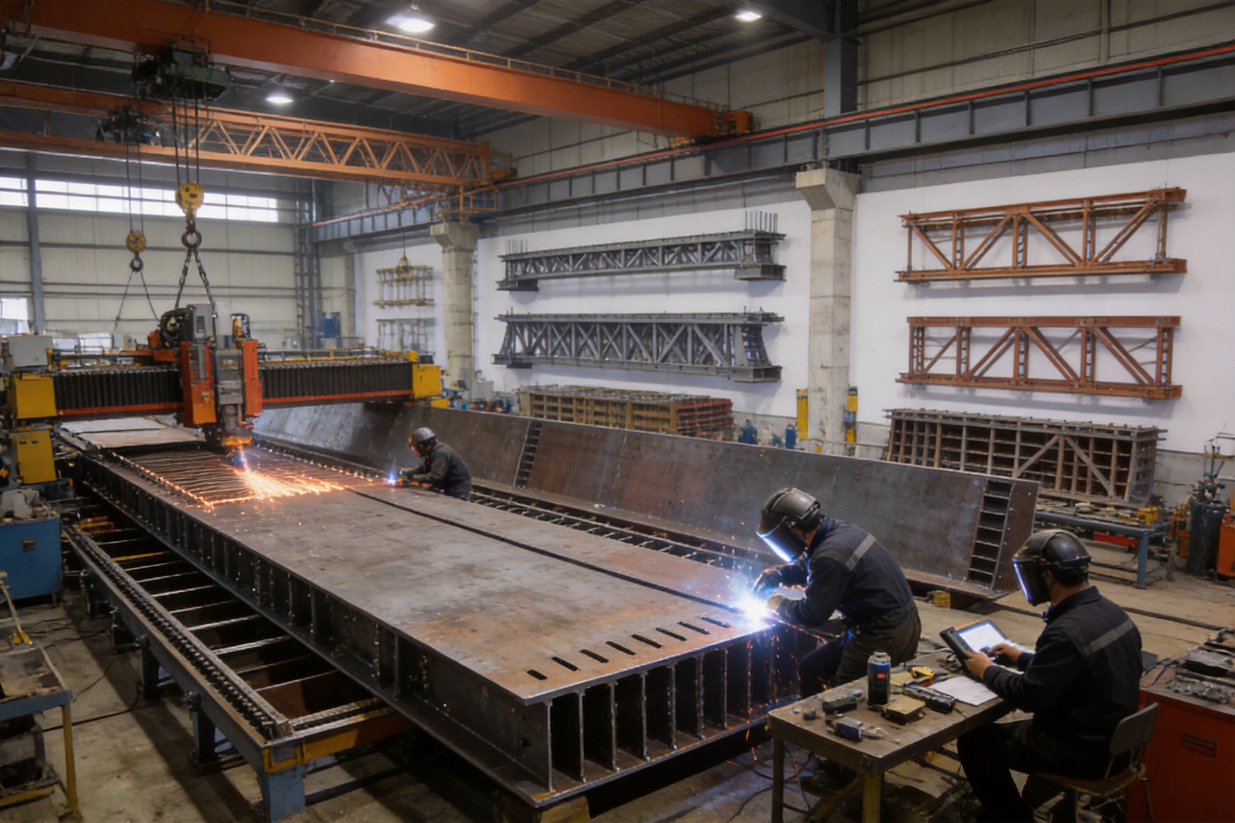
4. Advanced Manufacturing Process
The performance of box girder formwork depends strongly on the manufacturing process. A reliable supplier converts engineering drawings into accurately fabricated, properly welded, carefully finished, and thoroughly inspected steel components. Factory control is especially valuable for complex formwork because it reduces the number of uncertain operations that must be completed at the bridge site.
4.1 Engineering Review and Project Consultation
Manufacturing begins with a review of the bridge design, construction method, casting sequence, available lifting equipment, transport limitations, and expected reuse frequency. The supplier should understand whether the formwork will be used for cantilever casting, in-situ construction, or precast production.
Important design information includes the girder cross-section, casting length, concrete grade, reinforcement arrangement, prestressing system, expected pour rate, construction tolerances, access requirements, and stripping sequence. Early review helps identify conflicts between the formwork and ducts, anchors, embedded plates, reinforcement cages, scaffolding, or launching equipment.
For non-standard bridges, the formwork can be divided into modular units that balance structural performance with practical transportation and erection. The engineering team may also develop drawings for assembly, adjustment, lifting, inspection, and maintenance. This documentation supports safer and more consistent project execution.
4.2 Material Selection and Preparation
Steel material is selected according to structural requirements, weldability, environmental conditions, and the expected service life of the formwork. Plates, sections, stiffeners, brackets, and connection components must be compatible with the design loads and fabrication method.
Before cutting, material identification and dimensional checks are important. Surface condition should be reviewed, and plates should be free from excessive rust, laminations, or other defects that could affect fabrication. Proper material preparation supports stable welding and reduces later correction work.
4.3 Digital Detailing and Cutting
Complex box girder geometry benefits from computer-aided detailing. Digital models and fabrication drawings can define panel dimensions, bending lines, stiffener locations, bolt holes, access openings, and assembly references. Accurate detailing helps reduce cumulative dimensional errors, particularly where several panels meet at angled or curved joints.
Numerically controlled cutting equipment can produce repeatable plate shapes and openings. Accurate cutting improves fit-up and reduces the amount of manual grinding or site modification required. It also helps maintain consistency when multiple units of the same panel are manufactured.
4.4 Forming, Fit-Up, and Assembly
After cutting, plates may be formed, folded, or assembled with reinforcing members according to the design. Fit-up is performed on controlled work surfaces or assembly jigs where possible. These methods help ensure that the panel remains square, aligned, and dimensionally stable before welding.
Reference marks and assembly identifiers are useful for complex systems. Each modular unit can be labeled according to its position, orientation, and connection sequence. This reduces installation errors and makes inspection and replacement easier.
4.5 Welding Control
Welding is a critical part of steel formwork fabrication. Welded joints connect face plates to stiffeners, frames, brackets, and support members. Welding procedures should be selected according to material thickness, joint type, load requirements, and the need to limit distortion.
Controlled welding sequences help manage heat input and reduce warping. Where necessary, components can be temporarily restrained or supported during welding. Weld appearance, continuity, penetration, and surface condition should be checked according to the applicable project requirements.
Well-controlled welding provides more than strength. It also supports the flatness of the form face and the accuracy of adjacent joints. Excessive weld distortion can create gaps, misalignment, or local irregularities that later affect concrete surfaces.
4.6 Surface Treatment and Finishing
The concrete-contact surface should be smooth, clean, and free from sharp projections or unnecessary irregularities. Weld spatter, burrs, temporary attachments, and rough edges should be removed. Corners may be finished according to the required concrete profile, including chamfers or rounded details.
Protective coatings may be applied to non-contact steel surfaces according to the project environment and maintenance plan. Concrete-contact surfaces should be treated in a way that is compatible with release agents and does not transfer unwanted contaminants to the concrete. The specific coating system should be selected based on the intended use, storage conditions, and expected exposure.
4.7 Dimensional Inspection and Trial Assembly
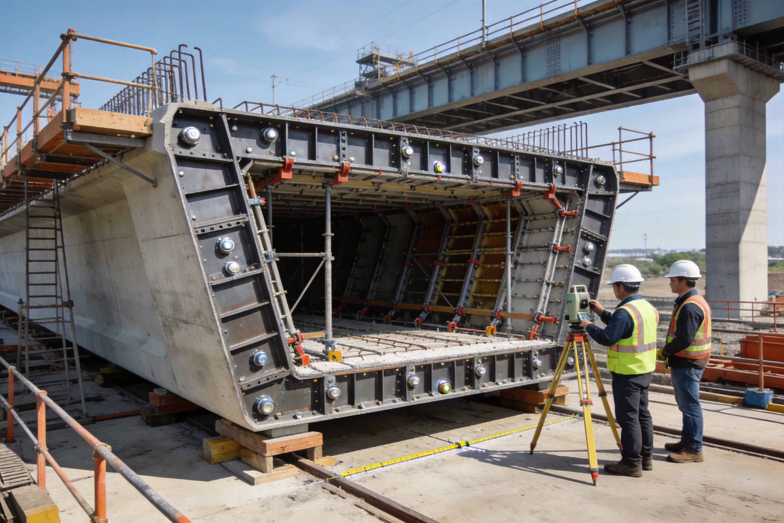
Inspection should verify overall dimensions, panel flatness, hole locations, connection interfaces, web angles, internal clearances, and the position of adjustment components. Measurements can be taken against approved drawings using calibrated instruments and suitable reference points.
For complicated or large systems, trial assembly is highly beneficial. A factory trial assembly can reveal interference between modules, difficult access points, incorrect connection orientation, or problems with the stripping sequence before the equipment is shipped. Corrections made in the factory are generally faster and less expensive than modifications performed at the construction site.
4.8 Packing, Transport, and Site Installation Support
Finished components should be packed according to their lifting points, fragility, and assembly order. Smaller accessories, bolts, seals, adjustment parts, and identification plates should be organized to prevent loss or confusion during transport.
Installation instructions, component lists, assembly drawings, and inspection checklists can accompany the shipment. Technical support during installation may help the site team understand panel orientation, adjustment procedures, joint sealing, and safe stripping practices.
5. Manufacturing Strengths of a Specialized Bridge Steel Supplier
A company that produces a broad range of bridge steel equipment can bring useful technical coordination to box girder formwork projects. Zhenjiang Jinhao Road & Bridge Supporting Engineering Co., Ltd. has developed from a supplier of construction and industrial materials into an enterprise involved in the design, manufacture, erection, and leasing of bridge-related steel systems.
Its product range includes Bailey steel bridges, Type 321 Bailey truss sections, HD200 or Type 200 Bailey truss sections, triangular and diamond hanging baskets, bridge launching gantry systems, pier formwork, bridge steel formwork, and related engineered structures. This product experience is relevant because box girder formwork often operates as part of a larger bridge construction system rather than as an independent item.
5.1 Integrated Understanding of Bridge Construction
Experience with launching gantries, hanging baskets, and temporary bridge systems helps a manufacturer understand the interaction between formwork, temporary supports, lifting arrangements, access platforms, and construction sequencing. This integrated perspective can improve the practicality of the final design.
For example, a formwork unit may need to fit within the operating envelope of a launching gantry, connect to a traveler, or be lifted by available site equipment. If these conditions are considered only after fabrication, modifications may be required. Early coordination makes it easier to design suitable lifting points, connection plates, working platforms, and modular dimensions.
5.2 Custom Design Capability
Bridge projects rarely have identical requirements. Cross-sections differ in width, depth, web angle, slab thickness, curvature, and diaphragm arrangement. Construction methods also vary according to terrain, traffic conditions, water crossings, project schedule, and available machinery.
Customized design allows the formwork to be adapted to the actual project rather than forcing the project to conform to a generic panel arrangement. A specialized supplier can evaluate the required casting length, reusable modules, internal form solution, adjustment range, transport dimensions, and erection sequence.
5.3 Fabrication and Erection Services
Providing both fabrication and erection support can improve continuity between the factory and the construction site. The same technical team can explain the intended assembly sequence, identify critical tolerances, and assist with initial alignment. When required, erection services can help the contractor reduce the learning curve associated with a new formwork system.
Technical support may include installation guidance, inspection procedures, troubleshooting, adjustment recommendations, maintenance advice, and replacement of damaged or worn components. These services are particularly useful for complex projects where formwork performance affects the entire construction schedule.
5.4 Quality Management and Traceability
Quality management should cover incoming steel, cutting, forming, welding, assembly, dimensional inspection, surface treatment, packing, and documentation. Traceability of materials and components supports accountability and makes it easier to identify the source of any issue.
Inspection records can include material certificates, welding records, dimensional reports, trial assembly records, coating information, and shipment lists. The precise documentation required depends on the contract and applicable standards, but organized records help contractors and owners verify that the formwork has been manufactured in accordance with the approved design.
5.5 Experience in Domestic and International Applications
Bridge steel products are used in varied environments, including transportation engineering, municipal construction, water conservancy, railway projects, and emergency or temporary access works. Experience across different applications encourages practical attention to transport, site access, weather, lifting, storage, and maintenance.
For overseas projects, communication, packaging, documentation, and coordination are especially important. A supplier serving international customers should be prepared to clarify technical requirements, adapt drawings to project practices, and support remote installation through organized instructions and responsive communication.
6. Comparison with Alternative Formwork Solutions
6.1 Compared with Timber Formwork
Timber formwork can be economical for simple shapes, small quantities, or projects where local materials and labor are readily available. However, box girders contain many complex surfaces and repeated geometric features. Timber systems may require extensive site fabrication, frequent adjustment, and replacement of components affected by moisture or repeated loading.
Steel box girder formwork generally provides greater rigidity, more consistent dimensions, and better repeatability. Its modular nature also makes it easier to plan for multiple casting cycles. For large bridge projects, these advantages can outweigh the higher initial investment.
6.2 Compared with Basic Steel Panels
Flat steel panels can be combined to form simple beams, but they may not provide an efficient solution for complex box girder geometry. Numerous improvised joints can increase the risk of leakage and make alignment more difficult. Local reinforcement added at the site may also create inconsistent stiffness.
Purpose-designed box girder formwork integrates the panel geometry, joint design, stiffening system, and adjustment mechanisms. This reduces the dependence on site modifications and helps create a more predictable construction process.
6.3 Compared with One-Piece Non-Modular Forms
A large one-piece form may appear simple because it has fewer joints, but it can create transportation, lifting, storage, and maintenance difficulties. It may also be unsuitable when the bridge cross-section changes or when the contractor needs to work in a restricted area.
Segmented modular formwork offers greater flexibility. Individual units can be transported more easily, replaced separately, and rearranged for compatible sections. The trade-off is that the joints must be carefully designed and maintained. With properly sealed interfaces, the modular approach can provide both flexibility and reliable concrete quality.
6.4 Compared with Low-Cost Unengineered Systems
Low-cost systems may reduce initial expenditure but create hidden costs through rework, leakage repair, slow assembly, dimensional corrections, and short service life. The total project cost should consider the number of casting cycles, labor requirements, concrete repair, schedule risk, and safety.
Engineered formwork competes not only on purchase price but also on total construction value. Its ability to support reliable production, consistent quality, and repeated use can make it more economical over the life of a major project.
7. Application in Different Construction Methods
7.1 Cantilever Casting
In balanced cantilever construction, box girder segments are cast progressively from piers using a traveler or hanging basket. Formwork must be compatible with the traveler structure and capable of accurately positioning each segment relative to the previously cast section.
The system should allow access for reinforcement, ducts, concrete placement, inspection, and finishing while keeping the weight of movable components within the capacity of the traveler. Adjustable connections are important because the elevation and alignment may change as the cantilever advances.
Joint sealing is critical at the interface between segments and around internal forms. Any leakage can interfere with the precision of the segment joint and create defects that are difficult to repair after the traveler has moved forward.
7.2 In-Situ Casting with Scaffolding
For in-situ construction on scaffolding, the formwork is supported by temporary works that transfer loads to the ground, piers, or other structural supports. The formwork must be aligned with the designed profile and adjusted for settlement, deflection, and construction camber.
The high rigidity of steel formwork helps maintain the cross-section during a large pour. However, the temporary support system must also be properly designed. Formwork strength cannot compensate for inadequate scaffolding, uneven foundations, or uncontrolled settlement.
7.3 Prefabrication Yard Production
In a precast yard, box girder formwork can be organized for repetitive production under controlled conditions. The casting bed, reinforcement preparation area, concrete supply, curing arrangement, and lifting equipment can be coordinated to establish a reliable production cycle.
Modular formwork is well suited to this method because the same units can be reused many times. The controlled environment makes it easier to inspect dimensions, clean surfaces, apply release agents, and maintain consistent concrete quality. Where several beam types are required, adjustable or interchangeable components can reduce the need for completely separate form systems.
7.4 Railway and Large-Span Applications
Railway and large-span bridges often impose strict requirements on geometry, load capacity, durability, and construction consistency. Box girder formwork must support accurate cross-sections and stable production while accommodating heavy reinforcement and prestressing systems.
For long bridges, small dimensional errors can accumulate across many spans or segments. A precise and repeatable formwork system helps control these risks. It also provides a practical foundation for inspection procedures that compare every casting cycle against approved references.
8. Quality Control During Construction
Even well-manufactured formwork must be correctly installed and maintained. Before each pour, the construction team should inspect the support system, panel connections, seals, dimensions, elevations, embedded items, and access arrangements.
8.1 Pre-Pour Inspection
Pre-pour inspection should confirm that all panels are securely connected and that adjustment devices are locked or otherwise protected from movement. The form surfaces should be clean and coated with a suitable release agent. Excessive release agent should be avoided because it may affect the concrete surface or interfere with subsequent finishes.
Joint seals should be continuous, properly compressed, and free from gaps. Special attention is required at corners, changes in section, diaphragm areas, and interfaces between internal and external forms. Any opening that could allow cement paste to escape should be corrected before concrete placement.
Measurements should verify web thickness, slab thickness, deck width, crossfall, elevation, alignment, and internal clearances. The inspection should also confirm that reinforcement, ducts, anchors, inserts, drainage components, and embedded plates do not conflict with the formwork.
8.2 Concrete Placement Control
Concrete should be placed according to an approved sequence that limits unbalanced pressure. Excessively rapid placement on one side of the form can produce uneven loading and movement. Vibration should be sufficient to achieve consolidation but controlled to avoid damaging joints or causing segregation.
Supervisors should watch for unusual movement, leakage, sound changes, or visible deformation during the pour. If a problem is detected, placement should be controlled or temporarily stopped while the cause is investigated. Early intervention can prevent a local issue from becoming a major defect.
8.3 Stripping and Relocation
Stripping should occur only after the concrete has achieved the required condition and the responsible engineer or project procedure permits removal. Premature stripping can damage corners, reduce surface quality, or impose unwanted stress on the young concrete.
Panels should be released in an orderly sequence. For internal forms, collapsible mechanisms or planned lifting points can reduce the risk of damaging the concrete opening. After removal, components should be cleaned, checked, and stored safely for the next cycle.
8.4 Maintenance and Storage
Concrete buildup should be removed without damaging the form face. Bolts, pins, hinges, braces, lifting points, and adjustment mechanisms should be inspected regularly. Bent members, cracked welds, worn threads, and damaged seals should be repaired or replaced before reuse.
Storage should protect panels from standing water, impact, excessive contamination, and uncontrolled deformation. Components should be supported at suitable points and arranged so that identification marks remain visible. Good storage practices preserve dimensional accuracy and reduce preparation time for the next casting cycle.
9. Selecting the Right Box Girder Formwork
Selection should begin with the bridge design and construction method rather than with a standard product name. The following factors should be evaluated before finalizing the system.
• Cross-sectional shape, including the number of cells, web inclination, slab thickness, and haunch details.
• Casting length and the number of expected reuse cycles.
• Concrete type, slump, placement speed, vibration method, and temperature conditions.
• Reinforcement congestion and the position of prestressing ducts and anchors.
• Available cranes, lifting capacity, transport dimensions, and site access.
• Required tolerances, construction camber, deck crossfall, and alignment control.
• Stripping sequence and the available space for removing internal forms.
• Compatibility with travelers, hanging baskets, launching gantries, scaffolding, or casting beds.
• Environmental exposure, storage requirements, and protective coating needs.
• Technical documentation, installation support, inspection procedures, and after-sales service.
A strong supplier should be able to discuss these factors before production begins. The goal is to deliver a system that is structurally adequate, practical to install, easy to adjust, and economically effective throughout the project.
10. Safety Considerations
Formwork safety involves more than the strength of the steel panels. Workers may operate at height, inside confined spaces, near lifting equipment, and around freshly placed concrete. The design should therefore include safe access, guardrails, working platforms, lifting points, inspection routes, and procedures for assembly and removal.
All lifting operations should use equipment and accessories with suitable capacity. Lifting points should be clearly identified, and the center of gravity of irregular modules should be understood before movement. Workers should not stand beneath suspended loads or enter areas where panels may shift unexpectedly.
Internal box girder spaces may have limited ventilation and restricted access. The construction plan should address lighting, communication, emergency escape, and inspection. Any release agent, coating, welding activity, or cleaning chemical should be managed according to the relevant safety requirements.
Safe design can also improve productivity. Clear access reduces unnecessary movement, organized connections shorten assembly time, and properly positioned lifting points reduce manual handling. Safety and efficiency are therefore complementary objectives rather than competing priorities.
11. Sustainability and Lifecycle Value
Reusable steel formwork can contribute to more sustainable bridge construction by reducing the consumption of disposable timber and minimizing repeated site fabrication. Its long service potential allows the same structural components to support multiple casting cycles or projects when properly maintained.
Modular design also supports repair rather than complete replacement. A damaged panel, seal, bracket, or adjustment device can often be replaced individually. This reduces material waste and keeps the remaining system in service.
Efficient formwork may reduce concrete repair, surface treatment, and rework. Better sealing and dimensional stability help limit defects that would otherwise require additional materials, labor, and time. In addition, factory fabrication can improve material utilization through controlled cutting and planned assembly.
At the end of its useful life, steel components can generally be recycled. The environmental performance of the system should be assessed across its full lifecycle, including manufacturing, transport, reuse, maintenance, and eventual recovery.
12. Why Project-Specific Engineering Matters
There is no single universal box girder formwork arrangement that is ideal for every bridge. A system designed for a short precast beam may not be suitable for a long balanced cantilever segment. A formwork unit intended for a regular cross-section may require significant modification for a variable-depth girder or a bridge with unusual diaphragm geometry.
Project-specific engineering helps ensure that loads, tolerances, access, transport, and construction sequence are considered together. It also allows the supplier to identify which components should be standardized and which should be customized.
Standardization remains valuable. Repeated panel sizes, common bolts, interchangeable seals, and consistent identification systems simplify fabrication and site management. The best result often combines standardized manufacturing principles with customized geometry and support arrangements.
13. Company Capabilities and Service Approach
Zhenjiang Jinhao Road & Bridge Supporting Engineering Co., Ltd. is located in Shangdang Town Industrial Park, Dantu District, Zhenjiang City, Jiangsu Province, China. Established in 2017, the company has expanded from construction and industrial material supply into the design, manufacturing, erection, and leasing of bridge-related steel systems.
The company’s capabilities cover Bailey bridges, Type 321 and HD200 or Type 200 Bailey truss components, launching gantry systems, hanging baskets, pier formwork, bridge steel formwork, and other engineered steel structures. This broad portfolio allows it to support projects involving temporary bridges, emergency access, semi-permanent structures, bridge erection, cantilever construction, and concrete forming.
Its service approach includes customized fabrication, design and system planning, technical support, and quality management. These services are important for box girder formwork because the equipment must be coordinated with the contractor’s construction method and the project’s structural requirements.
The company serves contractors, government-related projects, engineering companies, and infrastructure customers in different markets. Its stated operating principles emphasize customer-focused service, integrity, practical operation, innovation, cooperation, advanced technology, and sustainable development.
14. Frequently Asked Questions
Q1: What is box girder formwork used for?
Box girder formwork is used to create the external and internal geometry of concrete box girders. It forms the webs, top slab, bottom slab, internal voids, diaphragms, edges, and other specified features during in-situ, cantilever, or precast construction.
Q2: What is the main advantage of steel box girder formwork?
The main advantage is the combination of high rigidity, strong resistance to concrete pressure, accurate geometry, reliable joint sealing, and repeatable use. These properties support consistent beam quality and efficient construction over multiple casting cycles.
Q3: Can the formwork be customized for different cross-sections?
Yes. Box girder formwork can be designed for single-cell, twin-cell, or multi-cell sections and can accommodate different web angles, deck widths, slab thicknesses, diaphragms, haunches, and casting lengths. Adjustable and interchangeable components may be used where appropriate.
Q4: Is box girder formwork suitable for cantilever construction?
Yes. It can be integrated with a traveler, hanging basket, or other cantilever casting system. The formwork must be designed for the available equipment, segment dimensions, adjustment requirements, lifting capacity, and stripping sequence.
Q5: How does sealed joint design improve concrete quality?
Sealed joints reduce the escape of cement paste during casting. This helps prevent honeycombing, voids, fins, and other defects at panel interfaces. It also supports a denser concrete surface and reduces repair work after stripping.
Q6: What information should be provided when requesting a quotation?
Useful information includes the bridge type, cross-section drawings, casting length, construction method, concrete properties, expected reuse cycles, lifting limitations, required tolerances, project location, and desired technical services. More complete information allows the supplier to develop a more suitable proposal.
Q7: How is the formwork protected from deformation?
Deformation is controlled through appropriate plate thickness, stiffeners, frames, braces, supports, connection details, and adjustment systems. Manufacturing inspection and trial assembly also help confirm dimensional stability before shipment.
Q8: How often should the formwork be inspected?
It should be inspected before the first use, before every concrete pour, after stripping, after relocation, and whenever it has been overloaded, impacted, or exposed to unusual conditions. The inspection should cover panels, welds, bolts, seals, braces, lifting points, and adjustment devices.
Q9: Can internal formwork be collapsible?
Yes. Collapsible internal forms are often used where the box opening is restricted or where stripping space is limited. The mechanism must be designed for the cross-section, available access, expected loads, and safe removal sequence.
Q10: What makes a supplier suitable for an international bridge project?
A suitable supplier should combine engineering capability, controlled fabrication, dimensional inspection, organized documentation, reliable packing, technical communication, and support during installation. Experience with multiple bridge steel products can also help coordinate formwork with the wider construction system.
Q11: Is steel formwork more expensive than temporary timber formwork?
The initial purchase price may be higher, but total cost should include reuse, labor, installation time, repair, replacement, concrete defect correction, and schedule impact. For large or repetitive bridge projects, the durability and repeatability of steel formwork can provide better lifecycle value.
Q12: What maintenance is required?
Maintenance includes cleaning concrete residue, checking welds and structural members, lubricating or protecting adjustment devices, replacing damaged seals, inspecting bolts and lifting points, repairing surface damage, and storing modules on suitable supports.
15. Conclusion
Box girder formwork is a critical bridge construction system that directly influences structural geometry, concrete quality, construction speed, and project safety. Its value comes from the coordinated performance of rigid steel panels, reinforced frames, accurate adjustment mechanisms, modular connections, and sealed joints.
Compared with basic or improvised alternatives, engineered box girder formwork offers stronger resistance to lateral pressure, better dimensional stability, improved repeatability, and greater suitability for complex bridge sections. These advantages are particularly important for large-span highway and railway bridges, cantilever casting, in-situ construction, and standardized precast production.
The manufacturing process is equally important. Engineering review, digital detailing, controlled cutting, accurate fit-up, disciplined welding, surface finishing, dimensional inspection, trial assembly, and organized shipment all contribute to dependable field performance. A supplier with experience in bridge steel structures, launching systems, hanging baskets, pier formwork, and temporary bridge equipment can provide a broader understanding of how the formwork must function within the complete construction process.
Zhenjiang Jinhao Road & Bridge Supporting Engineering Co., Ltd. combines bridge steel manufacturing with design planning, customized fabrication, erection assistance, technical support, and quality management. Its product experience and project-oriented approach position it to supply box girder formwork for contractors and infrastructure organizations seeking reliable, reusable, and accurately engineered forming solutions.
When selecting a system, project owners and contractors should evaluate more than the initial quotation. Structural capacity, joint sealing, dimensional tolerances, casting sequence, reuse potential, safety, maintenance, installation support, and total lifecycle value should all be considered. With the right design and manufacturing partner, box girder formwork can provide a stable foundation for efficient bridge construction and long-term structural quality.
References
1. American Association of State Highway and Transportation Officials. AASHTO LRFD Bridge Design Specifications.
2. European Committee for Standardization. EN 12812, Falsework: Performance Requirements and General Design.
3. European Committee for Standardization. EN 1090, Execution of Steel Structures and Aluminium Structures.
4. International Federation for Structural Concrete. Model Code for Concrete Structures.
5. American Concrete Institute. ACI 347, Guide to Formwork for Concrete.
6. International Organization for Standardization. ISO 9001, Quality Management Systems.
7. International Organization for Standardization. ISO 3834, Quality Requirements for Fusion Welding of Metallic Materials.
8. Zhenjiang Jinhao Road & Bridge Supporting Engineering Co., Ltd. Product and company information supplied for technical content preparation.


 Français
 Español
 عربى