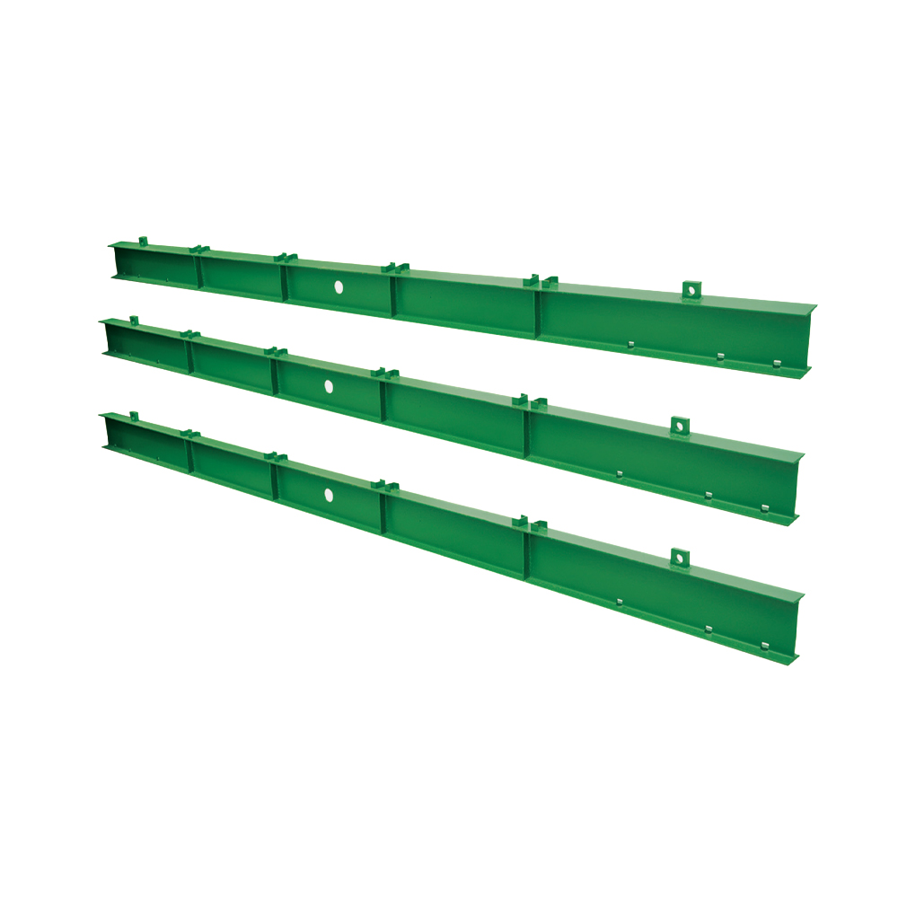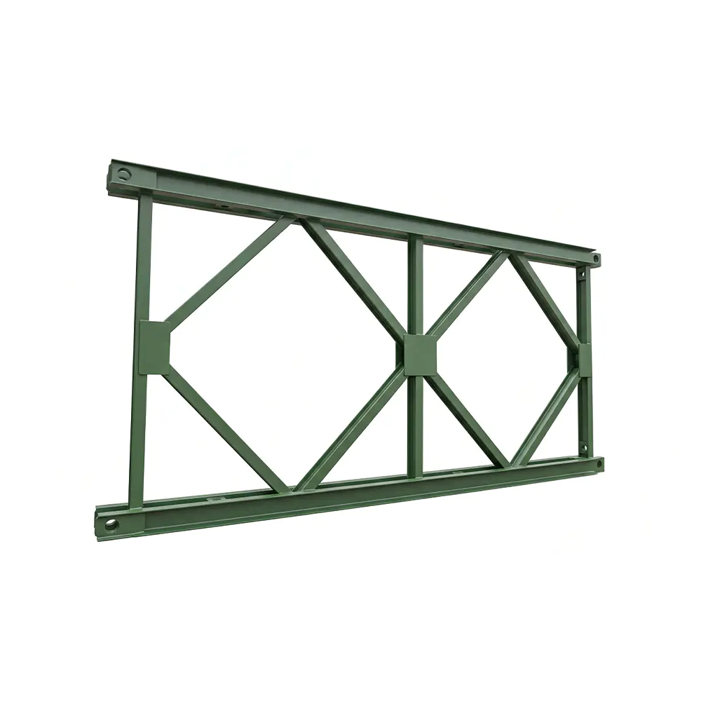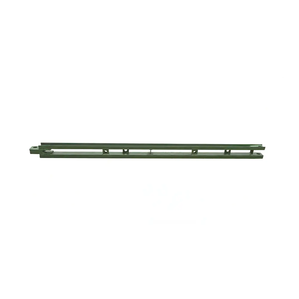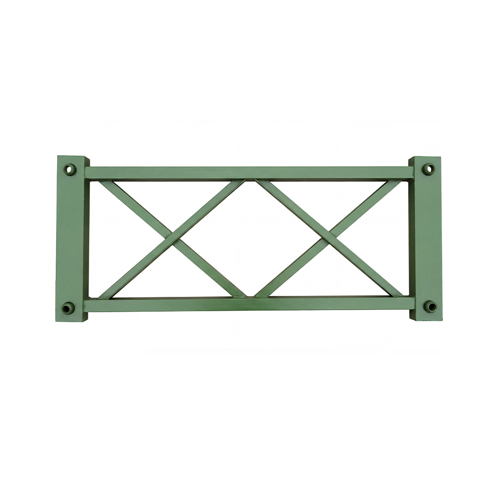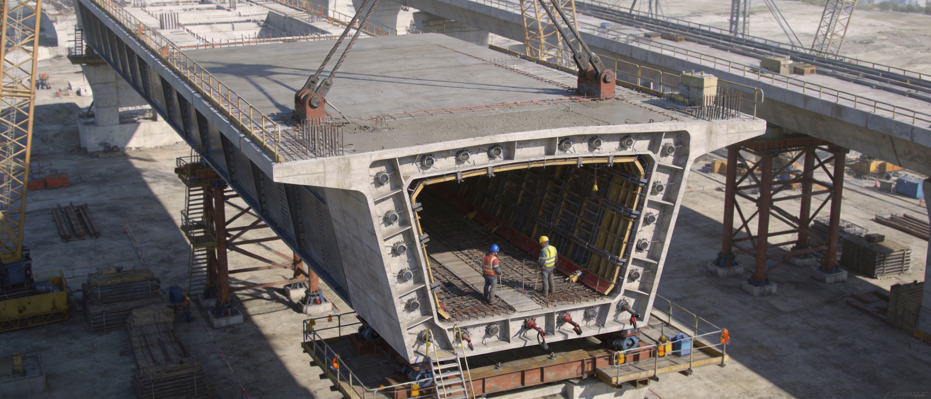
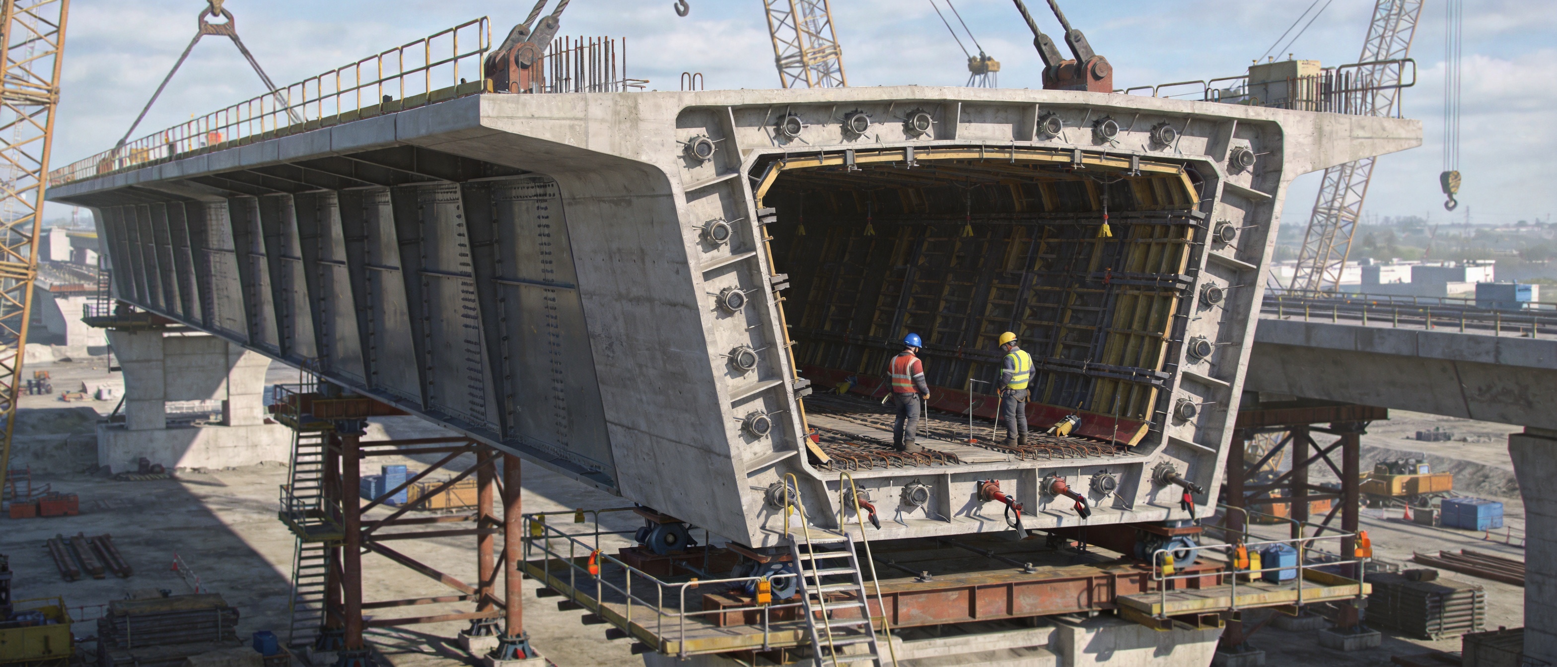
Box girder formwork is a specialized steel formwork system developed for the accurate, efficient, and repeatable construction of concrete box girder bridges. It provides the geometric support required to shape the web, top flange, bottom slab, diaphragms, cantilever sections, and other components of a box girder during concrete placement and curing. Because box girders combine complex cross-sections with demanding structural tolerances, the formwork must deliver more than a temporary enclosure. It must provide dimensional stability, resistance to fresh-concrete pressure, reliable sealing, safe access, controlled adjustment, and efficient dismantling or relocation.
Modern bridge projects increasingly require longer spans, heavier traffic loads, faster construction cycles, and improved consistency between individual segments. These requirements have made engineered steel formwork an important alternative to improvised timber systems or lightly reinforced temporary molds. A properly designed box girder formwork system helps contractors maintain the intended beam geometry while reducing concrete leakage, correcting fewer dimensional defects, and improving the overall productivity of the construction site.
Zhenjiang Jinhao Road & Bridge Supporting Engineering Co., Ltd. develops and manufactures bridge steel formwork and related bridge construction equipment for contractors, engineering companies, and infrastructure projects. Its product range includes box girder formwork, pier formwork, Bailey bridges, launching gantry systems, hanging baskets, and other fabricated steel structures. Through design, manufacturing, erection, leasing, and technical support, the company provides integrated solutions for different bridge construction methods and site conditions.
What Is Box Girder Formwork?
Box girder formwork is a temporary or reusable structural mold used to cast reinforced or prestressed concrete box girders. A box girder generally consists of one or more hollow cells formed by top and bottom slabs connected by vertical or inclined webs. Depending on the bridge design, the cross-section may also include diaphragms, side cantilevers, inspection recesses, drainage details, anchorage zones, and variations in depth or width.
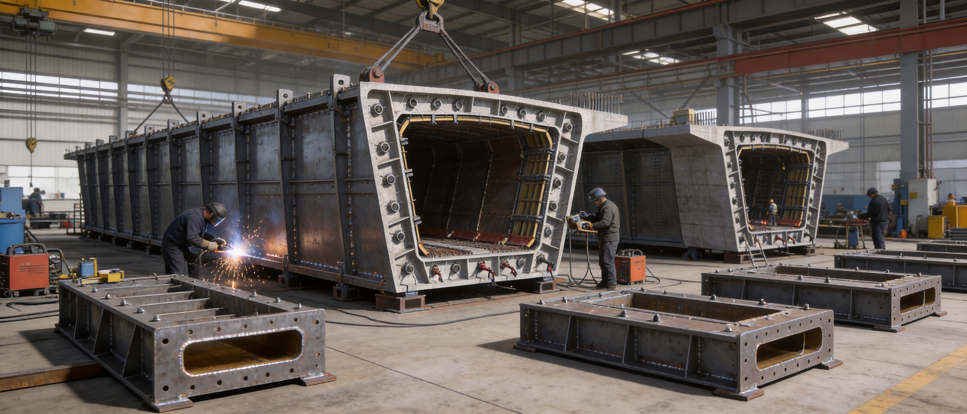
The formwork reproduces these features with a coordinated system of steel panels, stiffeners, support frames, working platforms, adjustment mechanisms, access components, and joint seals. The system can be installed for in-situ casting on scaffolding, adapted to segmental or cantilever construction, or configured for standardized production in a prefabrication yard. In each application, the primary objective is to maintain the designed shape while concrete is placed, vibrated, and cured.
Unlike simple flat formwork, box girder formwork must control several surfaces at the same time. The inner form defines the hollow portion of the girder, while the outer form shapes the exposed surfaces and flange edges. Web panels must remain aligned with the internal core, and the bottom form must resist the combined weight of the concrete, reinforcement, workers, equipment, and construction loads. The system must also permit reinforcement installation, prestressing duct placement, inspection, concrete pouring, and stripping without damaging the finished structure.
The use of steel allows the formwork to be designed as a robust, modular, and reusable system. Steel panels can be fabricated to precise dimensions, reinforced with welded stiffeners, and connected through bolts, pins, brackets, or engineered adjustment devices. This creates a more predictable construction process than systems assembled from irregular site materials.
Structural Components of a Box Girder Formwork System
External Form Panels
External form panels create the visible surfaces of the box girder, including the outside faces of the webs, bottom slab edges, flange edges, and cantilever portions. These panels are normally manufactured from steel plate supported by longitudinal and transverse stiffeners. The plate thickness, stiffener arrangement, and support spacing are selected according to the expected pressure of fresh concrete and the span between supporting members.
The external panels must retain their shape during pouring and vibration. Excessive deflection can produce dimensional deviations, uneven edges, or changes in the designed cross-section. For this reason, the panels are connected to support frames that transfer construction loads into the main supporting structure or foundation system.
Internal Core Form
The internal core forms the hollow cell or cells within the box girder. It is often one of the most technically demanding parts of the system because it must provide accurate internal dimensions while remaining accessible for installation and removal. Depending on the girder geometry, the core may include a collapsible mechanism, detachable sections, removable panels, or hydraulic and mechanical adjustment components.
A well-designed internal core balances rigidity with removability. It must be strong enough to resist concrete pressure but sufficiently practical to strip after the concrete reaches the required strength. Modular internal panels can also make it easier to accommodate changes in girder width, web inclination, or internal height.
Web and Flange Forms
The webs transfer forces between the top and bottom slabs and are essential to the structural behavior of the box girder. Web form panels must be positioned accurately because even small deviations can affect the thickness, alignment, and reinforcement cover of the finished member. Flange forms define the top deck slab and any side cantilever slabs, which frequently require careful control of width, slope, edge profile, and drainage details.
For complex cross-sections, the system is divided into coordinated segments. Each segment is fitted with connection plates, sealing elements, and adjustment points. This segmented approach makes the formwork easier to transport and install while allowing individual components to be inspected, repaired, or replaced.
Bottom Form and Support Structure
The bottom form supports the lowest surface of the girder and receives substantial loads during concrete placement. In an in-situ construction arrangement, the bottom form may be supported by scaffolding, steel beams, temporary towers, a launching gantry, or another engineered support system. In a prefabrication yard, it may rest on a fixed production bed or a reusable steel support frame.
The support structure must transfer loads safely to the ground or bridge support system. It must also limit settlement and vibration. If the support frame moves during casting, the resulting girder may develop an incorrect camber, uneven soffit, or dimensional mismatch with adjacent segments. Therefore, the formwork and its supporting system must be considered as one coordinated engineering package.
Adjustment and Access Equipment
Adjustment devices allow workers to control the horizontal position, vertical elevation, inclination, and width of the formwork. These devices may include screw jacks, threaded rods, wedges, hydraulic cylinders, sliding brackets, or bolted connection arrangements. Their purpose is to simplify initial alignment and compensate for small construction tolerances without requiring major disassembly.
Access platforms, guardrails, ladders, walkways, and working brackets are also important components. They provide safe access for reinforcement work, embedded-item installation, concrete inspection, joint cleaning, and form stripping. Properly integrated access equipment improves productivity and helps keep workers away from unsafe improvised platforms.
Why Box Girder Formwork Requires High Engineering Precision
Box girders are used in bridges where structural performance, span capability, stiffness, and efficient material use are important. Their hollow configuration reduces self-weight compared with a solid beam while retaining substantial bending and torsional capacity. However, this efficient structural shape leaves less room for construction errors. Variations in web thickness, slab thickness, internal dimensions, or alignment can influence reinforcement placement, prestressing operations, bearing interfaces, and the fit between adjacent components.
Fresh concrete produces lateral pressure on vertical and inclined surfaces. The pressure changes according to placement speed, concrete temperature, mix properties, vibration intensity, and the height of fluid concrete. If the formwork is too flexible or poorly supported, the panels may bulge, joints may open, or the cross-section may become distorted. Strong overall rigidity is therefore one of the principal advantages of a properly engineered steel system.
Concrete leakage is another major concern. Leaked cement paste can create fins, honeycombing, voids, rough edges, and defects around reinforcement or prestressing ducts. In severe cases, leakage can reduce the density of the concrete and require repair. A segmented, sealed-joint design helps prevent these problems by controlling the interfaces between web panels, flange panels, bottom forms, internal cores, and end sections.
Formwork precision also influences construction speed. A system that requires repeated site modification may appear inexpensive at the procurement stage but cause delays during assembly, inspection, correction, and stripping. By contrast, accurately fabricated modules can reduce fitting work, improve repeatability, and help crews follow a consistent operating sequence.
Key Advantages of Steel Box Girder Formwork
Strong Overall Rigidity
The most important advantage of steel box girder formwork is its ability to maintain its shape under demanding construction loads. Steel plates, welded stiffeners, support frames, and engineered connections work together to create a rigid assembly. This rigidity reduces panel deformation during concrete placement and supports more consistent control of the finished beam profile.
Compared with lightweight temporary molds, rigid steel formwork is better suited to large cross-sections, high pouring rates, deep webs, and heavy reinforcement cages. It can also withstand repeated use when it is inspected and maintained correctly. For projects involving many similar girders or segments, this durability can provide substantial operational value.
Excellent Resistance to Lateral Pressure
Fresh concrete behaves as a fluid during placement and creates lateral pressure on the side forms. The pressure can be especially significant when concrete is poured rapidly or when vibration is intensive. Steel formwork with a properly calculated stiffener pattern distributes this pressure through the panel and support structure.
Improved resistance to lateral pressure helps prevent bulging, joint opening, and misalignment. It also allows contractors to establish a more predictable pouring sequence. The formwork remains stable while concrete is placed in layers, compacted, and finished, reducing the need for emergency reinforcement or unplanned stoppages.
Sealed Segmented Joints
Box girder cross-sections contain numerous interfaces, and each interface can become a potential leakage path. The segmented joint design used in engineered formwork incorporates accurately machined or fabricated connection areas and sealing materials. When assembled correctly, these joints help retain cement paste and reduce surface defects.
Sealed joints are especially valuable around the web-to-flange transitions, bottom slab edges, internal core sections, construction joints, and end forms. By minimizing leakage, the system supports better concrete density and a cleaner finished surface. It also reduces the labor required for grinding, patching, and cosmetic repair after stripping.
Accurate Cross-Sectional Control
Steel components can be manufactured according to approved drawings and dimensional requirements. This allows the formwork to reproduce complex geometries, including inclined webs, variable flange widths, curved soffits, longitudinal slopes, and designated recesses. Adjustment points provide additional control during site installation.
Accurate geometry is important for both structural and construction reasons. It helps maintain reinforcement cover, supports correct placement of ducts and embedded items, and improves the fit between adjacent segments. It also contributes to a uniform appearance across a bridge project.
Reuse and Modular Adaptability
Many bridge projects involve repeated casting cycles. A modular steel system can be stripped, cleaned, moved, realigned, and reused. Depending on the design, selected panels may be replaced or adjusted to accommodate variations in girder length, width, depth, or cross-section.
Reuse can reduce the consumption of timber and other temporary materials. It can also produce more consistent results because the same engineered components are used throughout the project. Modular construction makes transportation and storage more manageable because large assemblies can be divided into practical sections.
Suitability for Multiple Construction Methods
Box girder formwork is suitable for several construction arrangements. For in-situ casting on scaffolding, the formwork is installed over a support system at the required elevation. For cantilever casting, it can be integrated with a hanging basket or other movable casting equipment. For prefabrication yards, it can be arranged on a fixed production bed or a reusable casting station.
This flexibility is an important advantage over formwork designed for only one site condition. Contractors can select a configuration based on span length, access limitations, construction sequence, environmental conditions, available lifting equipment, and project schedule.
Improved Construction Safety
Engineered formwork provides defined working surfaces, connection points, platforms, and guardrails. When combined with a documented erection and inspection procedure, it creates a more controlled work environment than ad hoc temporary arrangements. Stable platforms also make it easier for workers to perform reinforcement installation, concrete placement, inspection, and stripping activities.
Safety depends on correct engineering, installation, loading, and supervision. The formwork must be used within its design capacity, and all support conditions must be checked before concrete placement. Nevertheless, a purpose-built steel system provides a stronger foundation for safe working practices.
Comparison with Alternative Formwork Solutions
| Evaluation Factor | Steel Box Girder Formwork | Conventional Timber Formwork | Lightweight Panel Systems |
|---|
| Dimensional stability | High when properly designed, fabricated, and supported | More sensitive to moisture, workmanship, and repeated use | Depends on panel stiffness and support spacing |
| Resistance to concrete pressure | Suitable for large and complex box girder sections | Requires extensive reinforcement and frequent checking | Suitable only when loads remain within system capacity |
| Joint sealing | Segmented steel joints can be fitted with dedicated seals | Joint quality depends heavily on site assembly | Can be effective but may require special connectors |
| Reuse potential | High, especially for repeated bridge sections | Generally limited after multiple cycles | Moderate to high depending on system design |
| Complex geometry | Can be custom fabricated for webs, flanges, and internal cores | Flexible but labor-intensive and less repeatable | May require additional custom pieces |
| Site modification | Reduced when fabrication drawings are accurate | Often easy to modify but difficult to control precisely | Limited by standard panel dimensions |
| Large-span suitability | Strong option for heavy and high-precision bridge work | Less efficient for high-load or repeated large-span casting | Depends on the specific system and support arrangement |
Competitor systems may offer different combinations of standard panels, rental equipment, or specialized mechanisms. The practical advantage of a box girder formwork solution should therefore be assessed not only by the steel thickness or initial price, but also by engineering suitability, manufacturing accuracy, joint performance, installation requirements, reuse potential, technical support, and total project cost.
A low-cost system that requires extensive on-site modification can create hidden expenses. These may include additional labor, crane time, welding, grinding, seal replacement, concrete repair, re-alignment, and schedule delays. A professionally designed system may provide better value by reducing uncertainty throughout the construction cycle.
Manufacturing Process for Box Girder Formwork
Engineering Review and Configuration Development
The manufacturing process begins with a review of the bridge geometry, construction method, loading conditions, reuse requirements, and site restrictions. The formwork configuration must correspond to the approved structural drawings and the actual sequence of work. Important input includes the girder width, depth, web angle, slab thickness, flange projection, segment length, casting height, concrete placement rate, and support arrangement.
The engineering team also evaluates how the formwork will be delivered, lifted, assembled, adjusted, stripped, and relocated. A system intended for a prefabrication yard may differ from one designed for an elevated in-situ casting operation. A cantilever arrangement may require movable brackets, hanging equipment, or interfaces with a launching system.
At this stage, the company can develop customized drawings and system plans rather than forcing the project into an unsuitable standard configuration. Customization is particularly important where the box girder has a variable cross-section, curved alignment, unusual diaphragm arrangement, or demanding surface finish requirement.
Material Selection and Preparation
Steel materials are selected according to structural requirements, fabrication standards, environmental exposure, and project specifications. Plates, sections, stiffeners, brackets, connection components, and lifting points must be compatible with the intended load path and fabrication process.
Before cutting, materials are checked for identification, dimensions, surface condition, and visible defects. Proper material control helps ensure that the fabricated components correspond to the approved drawings. Plates may be prepared through shot blasting, mechanical cleaning, or other appropriate surface treatment before further processing or coating.
Computer-Aided Detailing
Detailed fabrication drawings translate the design concept into manufacturable components. These drawings define plate shapes, stiffener positions, bolt holes, weld locations, connection details, access openings, lifting points, adjustment interfaces, and sealing surfaces.
Computer-aided detailing helps coordinate the internal core, external forms, supports, and access equipment. It also reduces the risk of interference between reinforcement access zones, structural frames, connection brackets, and stripping paths. For complex bridge formwork, three-dimensional modeling can improve visualization and assembly planning.
Precision Cutting and Forming
Steel plates and sections are cut according to approved dimensions using suitable industrial equipment. Accurate cutting reduces the amount of secondary correction and helps maintain consistent module dimensions. Where curved or angled surfaces are required, plates may be formed, rolled, or assembled through controlled fabrication procedures.
Cut edges are inspected and prepared before assembly. Holes for bolts, pins, adjustment components, and lifting accessories are positioned according to the fabrication drawings. Accurate hole alignment is important because connection difficulties during site assembly can lead to delays and unauthorized modifications.
Assembly and Welding
Panels are assembled on a controlled fabrication surface or jig. Stiffeners are positioned to provide the required plate support and load transfer. Welded connections are completed using procedures suitable for the selected steel and component thickness. Welding sequence is managed to reduce distortion and preserve the designed flatness or curvature of the panel.
For large panels, temporary supports or assembly fixtures may be used to maintain geometry during welding. After welding, the components are checked for dimensional accuracy, frame squareness, connection alignment, and surface condition. Any distortion outside the approved tolerance must be corrected before the component proceeds to final assembly.
Joint and Seal Integration
Joint areas are prepared to achieve close contact between adjoining sections. Sealing strips, rubber components, compression seals, or other approved materials may be installed according to the project requirements. The purpose is to close gaps that could allow cement paste to escape during concrete placement.
Seal design must consider repeated stripping, cleaning, temperature changes, concrete residue, and handling damage. The joints should be accessible for inspection and replacement. A practical sealing system combines accurate steel fabrication with suitable consumable materials and correct installation procedures.
Trial Assembly and Quality Inspection
Before delivery, major formwork modules can be trial-assembled in the workshop or yard. Trial assembly verifies that panels, internal cores, supports, brackets, platforms, and connection components fit together as intended. It also helps identify lifting, transportation, and installation issues before the equipment reaches the bridge site.
Quality inspection may include dimensional measurement, weld inspection, visual examination, connection verification, surface checks, coating inspection, and functional testing of adjustment mechanisms. The inspection records provide traceability and help the contractor understand the correct assembly sequence.
Surface Treatment and Protection
Steel formwork is exposed to moisture, cement paste, handling, and outdoor storage. Appropriate surface preparation and protective coating can improve resistance to corrosion and extend service life. The concrete-contact surface should be smooth and treated in a manner compatible with the selected release agent and required concrete finish.
Coating systems must be applied to clean and properly prepared surfaces. Areas that will be welded or assembled on site may require specific treatment after installation. During transportation, exposed edges and machined surfaces should be protected against impact and contamination.
Manufacturing Strengths of an Integrated Bridge Equipment Supplier
Zhenjiang Jinhao Road & Bridge Supporting Engineering Co., Ltd. operates as a comprehensive bridge equipment enterprise rather than only a steel panel fabricator. Its activities cover design, manufacturing, erection, leasing, and technical support for bridge construction equipment. This integrated capability is valuable because formwork performance depends on the relationship between the panels, support system, construction sequence, and site operation.
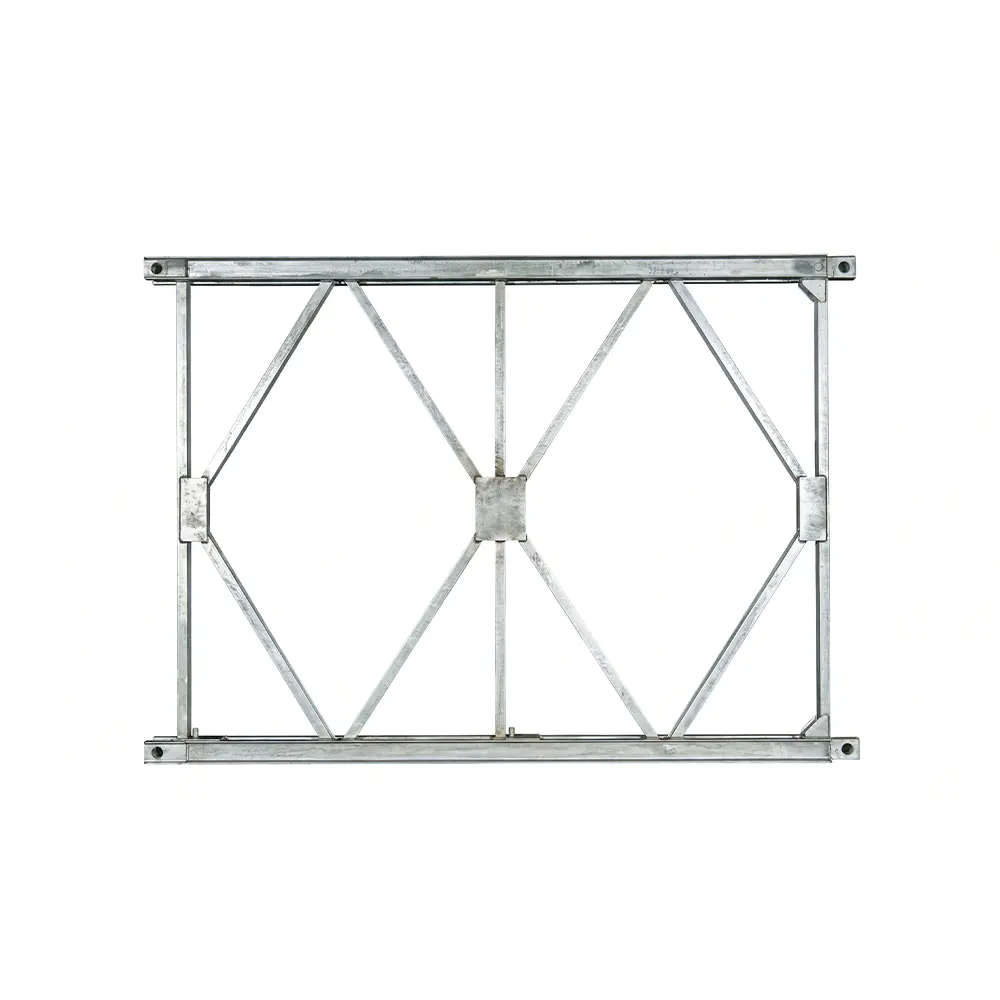
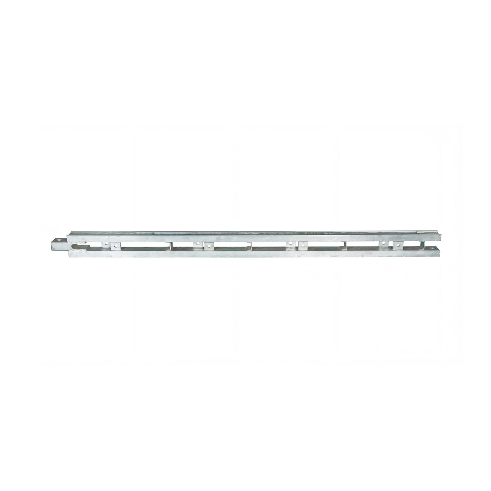
The company’s product experience includes Bailey steel bridges, Type 321 Bailey truss sections, HD200 and Type 200 Bailey truss sections, triangular and diamond hanging baskets, bridge launching gantry systems, pier formwork, box girder formwork, and related engineered steel structures. Experience across these product categories supports a broader understanding of temporary works, load transfer, modular steel fabrication, erection logistics, and bridge construction conditions.
For a box girder project, this wider capability can help coordinate formwork with a launching gantry, hanging basket, temporary support, access arrangement, or prefabrication process. Contractors can discuss not only the mold itself but also the practical requirements of moving, supporting, and operating the system.
The company was established in 2017 and is located in Shangdang Town Industrial Park, Dantu District, Zhenjiang City, Jiangsu Province, China. Its location near major transportation routes and the Beijing-Hangzhou Grand Canal supports the movement of fabricated steel products and project equipment. The company also emphasizes customized fabrication, system planning, technical assistance, quality management, and customer-oriented service.
Customization for Project Geometry
Bridge geometry varies widely between projects. A supplier with engineering and fabrication capabilities can customize the formwork for different girder widths, web slopes, slab thicknesses, casting lengths, and construction methods. This is more advantageous than relying solely on generic panels that may require extensive field adaptation.
Customization may include variable-depth sections, special end forms, diaphragm openings, anchorage zones, drainage details, access hatches, lifting points, adjustable side forms, and interfaces with temporary works. Each modification should be reviewed for structural adequacy, manufacturability, assembly practicality, and maintenance requirements.
Coordinated Production of Related Steel Systems
Box girder formwork may be only one part of a larger bridge construction package. Where the same supplier can manufacture related steel systems, coordination may be simplified. Connection dimensions, support interfaces, working platforms, lifting arrangements, and movement paths can be reviewed together.
This integrated approach can reduce the risk of mismatched components. It also provides contractors with a single technical channel for questions concerning fabrication, delivery, erection, operation, and maintenance.
Technical Support and Erection Assistance
Formwork must be correctly assembled and adjusted to perform as designed. Technical support can include assembly drawings, component lists, lifting plans, adjustment instructions, inspection checklists, and operational guidance. For projects requiring additional assistance, erection support or on-site technical coordination can help the contractor establish the system more efficiently.
Support should continue through the casting cycle. The team may advise on pre-pour inspection, joint sealing, release-agent application, concrete placement sequence, vibration control, stripping time, cleaning, and relocation. This practical guidance helps protect the formwork and improve the consistency of finished concrete.
Applications in Bridge Construction
Large-Span Highway Bridges
Highway bridges often require wide decks, substantial traffic loads, and durable structural elements. Box girders are suitable for many highway alignments because their closed cross-section provides stiffness and a clean external profile. Steel formwork supports the accurate construction of the webs and slabs while accommodating reinforcement, prestressing ducts, drainage features, and deck details.
For repeated highway spans, reusable formwork can help establish a regular production cycle. Once the first casting operation has been checked and refined, the system can be transferred to subsequent locations while maintaining a consistent geometry.
Railway Box Girder Bridges
Railway bridges typically involve strict alignment, deflection, durability, and structural precision requirements. Box girder formwork can be adapted to support the controlled production of railway beam sections, whether the work occurs in a casting yard or on site.
In railway applications, accuracy must be coordinated with bearing locations, track geometry, expansion arrangements, inspection access, and prestressing details. The formwork should therefore be manufactured and installed in accordance with the project’s dimensional and quality-control requirements.
Cantilever Casting
Cantilever construction is used where ground access is limited, river navigation must be maintained, or long spans make full scaffolding impractical. In this method, concrete segments are cast progressively from piers or previously completed segments. Box girder formwork may be integrated with a hanging basket or other movable casting system.
The formwork must be sufficiently rigid to maintain the cross-section while suspended or supported at elevation. It must also be designed for repeated movement, accurate positioning, rapid adjustment, and safe access. The interface between the formwork and the cantilever equipment must be checked carefully before each casting cycle.
In-Situ Casting on Scaffolding
Where ground conditions, water levels, traffic arrangements, and construction height permit, box girders may be cast in situ on scaffolding. In this arrangement, the formwork is installed above a temporary support system. The main challenges include foundation settlement, support stability, elevation control, and access for reinforcement and concrete placement.
Steel formwork provides a stable casting surface and can be adjusted to the required camber or alignment. The scaffolding and formwork should be inspected together because movement in the support system directly affects the formwork geometry.
Prefabrication Yards
Prefabrication yards provide controlled conditions for producing standardized box girder sections. A reusable steel formwork system can support repeated casting operations, organized reinforcement installation, quality inspection, curing, and lifting.
In a yard environment, the formwork may be mounted on a fixed bed, a movable platform, or a production line. The design can include quick-release connections, replaceable seals, integrated access platforms, and lifting interfaces. Repetition makes it especially important to control wear, cleaning, release-agent application, and dimensional verification after every cycle.
Installation and Operating Procedure
Site Preparation
Before formwork assembly, the contractor should verify the foundation, support frame, scaffolding, casting bed, or launching equipment. The supporting surface must be capable of carrying the calculated loads without excessive settlement. Survey control points should be established to guide the alignment and elevation of the system.
All components should be checked against the packing list and assembly drawings. Damaged plates, bent connection parts, missing bolts, worn seals, or contaminated contact surfaces should be identified before installation.
Assembly of Main Modules
Modules are assembled according to the approved sequence. Depending on the site arrangement, the bottom form may be installed first, followed by external web panels, the internal core, flange forms, end forms, platforms, and adjustment devices. Lifting operations should use designated lifting points and suitable equipment.
Connections must be tightened or secured according to the system requirements. Unauthorized field cutting, drilling, or welding can reduce structural capacity or interfere with later reuse. If modifications are necessary, they should be reviewed by the responsible technical team.
Alignment and Adjustment
After assembly, the formwork is surveyed in three dimensions. Checks normally include centerline, width, elevation, cross-section, web inclination, flange projection, end position, and camber. Adjustment devices are used to bring the system within the specified tolerance.
The internal core and external forms should be checked together. Correct external dimensions do not guarantee correct internal dimensions, and the web thickness must be verified at several locations. Survey results should be recorded before reinforcement and embedded items obstruct access.
Pre-Pour Inspection
Before concrete placement, the formwork should be cleaned and the concrete-contact surfaces treated with an approved release agent. Joints must be closed and sealed. Reinforcement, prestressing ducts, inserts, drainage components, and embedded plates should be checked for position and clearance.
Support frames, bolts, braces, platforms, guardrails, lifting devices, and adjustment mechanisms should also be inspected. Any standing water, debris, loose material, or excess release agent should be removed. A formal pre-pour checklist helps ensure that critical details are not overlooked.
Concrete Placement
Concrete should be placed according to a sequence that limits unbalanced loading. Excessively rapid placement on one side of the form may create uneven pressure and temporary distortion. Vibration should achieve adequate compaction without striking reinforcement, ducts, seals, or embedded items.
Operators should observe the formwork during pouring. Signs of movement, unusual noise, joint opening, leakage, or support settlement require immediate attention. Work should be stopped if the system exceeds the approved operating condition.
Stripping and Relocation
Formwork should not be stripped until the concrete has reached the required strength and the responsible engineer or site authority has approved the operation. Stripping should proceed in a controlled sequence that avoids impact on corners, edges, ducts, and finished surfaces.
After removal, the panels should be cleaned without damaging the steel or sealing surfaces. Concrete residue should not be allowed to accumulate on connection areas. Components should be inspected, lubricated where necessary, repaired if required, and stored in a manner that prevents distortion and corrosion before the next casting cycle.
Quality Control and Performance Management
Quality control begins with design verification and continues through material procurement, fabrication, trial assembly, delivery, erection, operation, and maintenance. Each stage affects the final performance of the box girder formwork.
Dimensional control is particularly important. Measurements should verify panel length, width, curvature, hole locations, frame alignment, internal core dimensions, and connection positions. Welding quality should be examined according to the project’s inspection requirements. Critical welds may require non-destructive testing where specified.
Joint performance should be checked before concrete placement. Seals must be continuous, correctly positioned, and free from damage. Where the system is reused, the contractor should inspect seal compression and replace worn components rather than relying on temporary patching.
Coating and surface condition should also be monitored. Scratches and exposed steel should be repaired before extended storage or use in wet environments. Concrete-contact surfaces should remain sufficiently smooth to support the required finish and easy stripping.
Operational records can improve long-term performance. Useful records include casting dates, reuse cycles, repair history, alignment measurements, seal replacement, coating maintenance, and observations during concrete placement. These records help identify recurring issues and support planned maintenance rather than emergency repair.
How the System Can Improve Project Economics
The economic value of box girder formwork is determined by the total construction process rather than only the purchase price. A robust system can reduce labor associated with repeated adjustment, repair, and rework. Accurate panels can also reduce concrete surface defects and the cost of corrective treatment.
Reuse is another important factor. When a formwork system serves many casting cycles, the initial fabrication cost is distributed across a larger production volume. Modular parts can be repaired or replaced selectively, which may be more economical than rebuilding an entire temporary mold.
Productivity improvements may come from faster assembly, easier alignment, predictable stripping, and reduced waiting time between casting operations. In a prefabrication yard, the system can support a planned production rhythm. In an in-situ project, it can reduce the time required to prepare the next casting position.
Logistics should be considered as well. A modular system that can be transported in manageable sections may reduce special handling requirements. Clearly identified components and standardized connection details can simplify inventory control and site organization.
These benefits depend on appropriate design and disciplined operation. A formwork system cannot compensate for inadequate support, poor concrete practice, incorrect reinforcement placement, or insufficient inspection. The best results are achieved when the supplier, contractor, designer, and site supervision team coordinate from the beginning.
Environmental and Sustainability Considerations
Steel formwork can support more sustainable bridge construction through repeated use and long service life. Reusable panels reduce dependence on disposable timber and minimize the volume of temporary materials sent to waste. A durable steel system can be repaired, refurbished, relocated, or adapted for future projects.
Efficient formwork also contributes indirectly to resource conservation. Better joint sealing can reduce concrete loss, while improved dimensional accuracy can reduce the need for repair materials. A predictable casting process may decrease rework, additional transportation, and energy consumption associated with corrective operations.
At the end of its service life, steel components can generally be recovered and recycled. Responsible maintenance extends the usable life of the system and improves the value obtained from the original materials. Protective coatings, correct storage, and timely repair are therefore both economic and environmental measures.
Selection Guide for Contractors and Engineering Companies
Confirm the Construction Method
The first selection step is to define whether the box girder will be cast on scaffolding, produced in a prefabrication yard, constructed by cantilever casting, or formed through another specialized method. The formwork support, movement, access, and stripping requirements depend on this decision.
Review the Complete Geometry
Contractors should provide complete cross-sectional information rather than only nominal beam width and depth. Web inclination, flange projection, bottom slab shape, internal cells, diaphragms, variable sections, end details, curves, slopes, and construction joints all influence the formwork design.
Evaluate Reuse Requirements
The expected number of casting cycles affects material selection, connection design, seal specification, surface treatment, and maintenance planning. A project with repeated sections may benefit from a highly modular system with quick adjustment and relocation features.
Check Support and Lifting Conditions
The formwork must be compatible with the available scaffolding, casting bed, gantry, crane, lifting capacity, transport route, and storage area. Weight and module dimensions should be reviewed before fabrication to avoid site handling problems.
Ask for Technical Documentation
Important documents may include general arrangement drawings, fabrication drawings, component schedules, material information, welding and inspection records, assembly instructions, lifting recommendations, adjustment procedures, maintenance guidance, and pre-pour checklists.
Consider Total Cost of Ownership
Purchase price is only one part of the evaluation. Contractors should also consider freight, erection, labor, expected reuse, cleaning, seal replacement, repairs, storage, technical support, and possible rental or leasing arrangements. A system that performs consistently may provide a lower total cost even if its initial price is not the lowest quotation.
Frequently Asked Questions
What is the main purpose of box girder formwork?
The main purpose is to create and maintain the designed shape of a concrete box girder during reinforcement installation, concrete placement, vibration, curing, and stripping. It forms the external surfaces, internal hollow areas, webs, flanges, bottom slab, and other required details.
Why is steel preferred for large box girder projects?
Steel provides high rigidity, strong resistance to concrete pressure, dimensional stability, durability, and good reuse potential. It can also be fabricated into customized panels and support frames for complex cross-sections and repeated casting cycles.
Can box girder formwork be used for both highway and railway bridges?
Yes. The system can be customized for highway and railway box girders, provided that the formwork geometry, load capacity, dimensional tolerances, support arrangement, and construction sequence comply with the relevant project requirements.
Is box girder formwork suitable for cantilever casting?
Yes. It can be integrated with a hanging basket or another cantilever casting arrangement. The design must account for suspended loads, movement, adjustment, access, repeated cycling, and the connection between the formwork and the supporting equipment.
Can the formwork be used in a prefabrication yard?
Yes. It can be installed on a fixed casting bed, reusable production platform, or other yard-based support system. Modular steel panels are particularly useful where many standardized box girder sections must be produced with consistent dimensions.
How does sealed joint design reduce concrete defects?
Sealed joints close the interfaces between formwork sections and reduce the escape of cement paste during concrete placement. This helps prevent fins, honeycombing, voids, and rough edges, while supporting a denser and more uniform concrete surface.
What information is needed to design customized formwork?
Typical information includes cross-sectional drawings, girder length, web and slab dimensions, flange projection, internal cell arrangement, diaphragms, construction method, casting height, support conditions, expected concrete pressure, reuse requirements, site access, lifting capacity, and required tolerances.
How many times can steel formwork be reused?
The number of reuse cycles depends on the design, material quality, loading, handling, cleaning, storage, coating condition, and maintenance. Properly engineered and maintained steel formwork can be reused for multiple casting cycles, but every cycle should include inspection and correction of damaged components.
What should be checked before concrete pouring?
The contractor should check alignment, elevation, dimensions, support stability, connection security, seals, release agent, reinforcement clearance, prestressing ducts, embedded items, access platforms, guardrails, cleanliness, and the condition of all adjustment devices.
Why is technical support important?
Correct assembly and operation are essential to formwork performance. Technical support helps the contractor understand the component layout, erection sequence, adjustment procedure, load limitations, pre-pour inspection, stripping method, maintenance requirements, and safe relocation process.
Can the system be leased instead of purchased?
Depending on the project arrangement, bridge formwork and related steel equipment may be available through leasing or rental services. Leasing can be useful when the contractor needs specialized equipment for a limited project duration or wants to reduce the initial capital investment.
What makes one box girder formwork supplier stronger than another?
Important factors include engineering capability, fabrication accuracy, quality control, material traceability, customization, joint design, support integration, delivery reliability, erection assistance, after-sales service, and experience with related bridge equipment. The supplier should be evaluated on complete project performance rather than product appearance alone.
Conclusion
Box girder formwork is a critical component in the construction of large-span highway and railway bridges. Its performance directly affects cross-sectional accuracy, concrete quality, construction speed, worker safety, and the cost of corrective work. Strong overall rigidity and resistance to lateral pressure enable the system to withstand demanding casting conditions, while segmented sealed joints help prevent concrete leakage and improve the density and appearance of the finished beam.
Compared with improvised timber molds or unsuitable lightweight systems, engineered steel box girder formwork offers greater dimensional stability, higher reuse potential, improved adaptability, and better suitability for complex cross-sections. It can support cantilever casting, in-situ casting on scaffolding, and standardized prefabrication-yard production.
Zhenjiang Jinhao Road & Bridge Supporting Engineering Co., Ltd. combines steel fabrication with bridge equipment design, erection, leasing, and technical support. Its experience with Bailey bridges, launching gantry systems, hanging baskets, pier formwork, and other engineered structures provides a broad foundation for developing practical bridge construction solutions. For contractors seeking dependable box girder formwork, the most valuable qualities are accurate engineering, controlled manufacturing, reliable sealing, robust support, efficient operation, and responsive technical cooperation.
When these qualities are combined, box girder formwork becomes more than a temporary mold. It becomes a repeatable production system that helps bridge builders achieve precise geometry, durable concrete structures, improved site efficiency, and reliable performance across demanding infrastructure projects.
References
1. American Association of State Highway and Transportation Officials. LRFD Bridge Design Specifications.
2. American Concrete Institute. Guide to Formwork for Concrete.
3. fib, International Federation for Structural Concrete. Model Code for Concrete Structures.
4. European Committee for Standardization. Execution of Concrete Structures.
5. International Organization for Standardization. Quality Management Systems: Requirements.
6. International Organization for Standardization. Welding Quality Requirements for Fusion-Welded Metallic Materials.
7. Concrete Society. Guidance on Formwork for Concrete Construction.
8. Bridge construction and temporary works engineering manuals concerning falsework, formwork stability, concrete placement, and segmental bridge construction.


 Français
 Español
 عربى